Bond SP01 - - Strain Penetration Model for Fully Anchored Steel Reinforcing Bars
- Command_Manual
- Tcl Commands
- Modeling_Commands
- model
- uniaxialMaterial
- ndMaterial
- frictionModel
- section
- geometricTransf
- element
- node
- sp commands
- mp commands
- timeSeries
- pattern
- mass
- block commands
- region
- rayleigh
- Analysis Commands
- Output Commands
- Misc Commands
- DataBase Commands
This command is used to construct a uniaxial material object for capturing strain penetration effects at the column-to-footing, column-to-bridge bent caps, and wall-to-footing intersections. In these cases, the bond slip associated with strain penetration typically occurs along a portion of the anchorage length. This model can also be applied to the beam end regions, where the strain penetration may include slippage of the bar along the entire anchorage length, but the model parameters should be chosen appropriately.
| uniaxialMaterial Bond_SP01 $matTag $Fy $Sy $Fu $Su $b $R |
This model is for fully anchored steel reinforcement bars that experience bond slip along a portion of the anchorage length due to strain penetration effects, which are usually the case for column and wall longitudinal bars anchored into footings or bridge joints
| $matTag | integer tag identifying material |
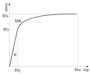
| $Fy | Yield strength of the reinforcement steel |
| $Sy | Rebar slip at member interface under yield stress. (see NOTES below) |
| $Fu | Ultimate strength of the reinforcement steel |
| $Su | Rebar slip at the loaded end at the bar fracture strength |
| $b | Initial hardening ratio in the monotonic slip vs. bar stress response (0.3~0.5) |
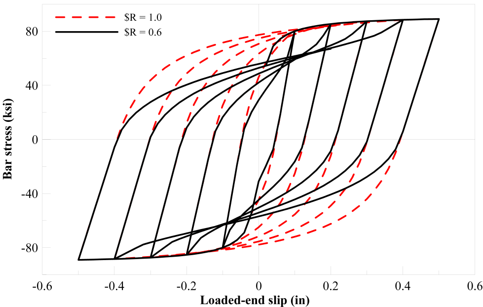
| $R | Pinching factor for the cyclic slip vs. bar response (0.5~1.0) |
Monotonic bar stress vs. slip response as modelled in Bond_SP01
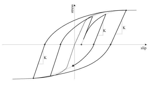
Cyclic bar stress vs. slip response as modelled in Bond_SP01
Pinching effect represented by $R in Bond_SP01
NOTES:
$Sy Rebar slip at member interface under yield stress and may be obtained from
or
where:
- db is rebar diameter
- $Fyis yield strength of the reinforcement steel
- fc' is concrete compressive strength of the adjoining connection member
- alpha is a parameter used in the local bond-slip relation and can be taken as 0.4 in accordance with CEB-FIP Model Code 90
Model background:
Capturing the structural response and associated damage require accurate modeling of localized inelastic deformations occurring at the member end regions as identified by shaded areas in Figure 4. These member end deformations consist of two components: 1) the flexural deformation that causes inelastic strains in the longitudinal bars and concrete, and 2) the member end rotation, as indicated by arrows in Figure 4, due to reinforcement slip. The slip considered here is the result of strain penetration along a portion of the fully anchored bars into the adjoining concrete members (e.g., footings and joints) during the elastic and inelastic response of a structure. Ignoring the strain penetration component may appear to produce satisfactory force-displacement response of the structural system by compromising strain penetration effects with greater contribution of the flexural action at a given lateral load. However, this approach will appreciably overestimate the strains and section curvatures in the critical inelastic regions of the member, and thereby overestimate the structural damage.
Figure 4: Expected inelastic regions at the column and wall ends
The zero-length section element available in OpenSees may be used to accurately model the strain penetration effects (or the fixed end rotations shown in Figure 4). Zero-length section elements have been generally used for section analyses to calculate the moment corresponding to a given curvature. To model the fixed-end rotation, the zero-length section element should be placed at the intersection between the flexural member and an adjoining member representing a footing or joint as shown in Figure 5. A duplicate node is also required between a fiber-based beam-column element and the adjoining concrete element as shown in Figure 5. The translational degree-of-freedom of this new node (i.e., node j in Figure 5) should be constrained to the other node (i.e., node i in Figure 5) to prevent sliding of the beam-column element under lateral loads because the shear resistance is not included in the zero-length section element.
Figure 5: Adding a zero-length section element to a beam-column element
The zero-length section element in OpenSees is assumed to have a unit length such that the element deformations (i.e., elongation and rotation) are equal to the section deformations (i.e., axial strain and curvature). The material model for the steel fibers in the zero-length section element represents the bar slip instead of strain for a given bar stress. The uniaxial material model Bond_SP01 is developed for steel fibers in the zero-length section elements.
Note on Material Model for Concrete Fibers
Similar to the model proposed for the steel fibers, a material model describing the monotonic response and hysteretic rules is also required for the concrete fibers. The combination of using the zero-length section element and enforcing the plane section assumption at the end of a flexural member impose high deformations to the extreme concrete fibers in the zero-length element. These deformations would likely correspond to concrete compressive strains significantly greater than the strain capacity stipulated by typical confined concrete models. Such high compressive strains at the end of flexural members are possible because of additional confinement effects expected from the adjoining members and because of complex localized deformation at the member end. Without further proof, it is suggested that the concrete fibers in the zero-length section element follow a concrete model in OpenSees (e.g., Concrete02). To accommodate the large deformations expected to the extreme concrete fibers in the zero-length element, this concrete model may be assumed to follow a perfectly plastic behavior once the concrete strength reduces to 80% of the confined compressive strength. A parametric study has indicated that the simulation results would not be very sensitive to the compressive strain chosen to trigger the perfectly plastic behavior for the concrete fibers in the zero-length section element.
REFERENCES:
- Zhao, J., and S. Sritharan. (2007) Modeling of strain penetration effects in fiber-based analysis of reinforced concrete structures. ACI Structural Journal, 104(2), pp. 133-141.
WEBSITE:
Code Developed by: Jian Zhao, University of Wisconsin, Milwakee
and Sri Sritharan, Iowa State University


