uniaxialMaterial PinchingLimitStateMaterial $matTag $nodeT $nodeB $driftAxis $Kelas $crvTyp $crvTag|}
| $YpinchUPN $YpinchRPN $XpinchRPN
$YpinchUNP $YpinchRNP $XpinchRNP
$dmgStrsLimE $dmgDispMax
$dmgE1 $dmgE2 $dmgE3 $dmgE4 $dmgELim
$dmgR1 $dmgR2 $dmgR3 $dmgR4 $dmgRLim $dmgRCyc
$dmgS1 $dmgS2 $dmgS3 $dmgS4 $dmgSLim $dmgSCyc
|
| $matTag |
unique material object integer tag
|
| $nodeT |
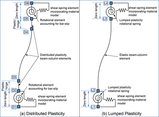
integer node tag to define the first node at the extreme end of the associated flexural frame member (L3 or D5 in Figure)
|
| $nodeB |
integer node tag to define the last node at the extreme end of the associated flexural frame member (L2 or D2 in Figure)
|
| $driftAxis |
integer to indicate the drift axis in which lateral-strength degradation will occur. This axis should be orthogonal to the axis of measured rotation (see $rotAxis in Rotation Shear Curve definition)
driftAxis = 1 – Drift along the x-axis
driftAxis = 2 – Drift along the y-axis
driftAxis = 3 – Drift along the z-axis
|
| $Kelas |
floating point value to define the initial material elastic stiffness (Kelastic); Kelas > 0
|
| $crvTyp |
integer flag to indicate the type of limit curve associated with this material.
crvTyp = 0 – No limit curve
crvTyp = 1 – axial limit curve
crvTyp = 2 – RotationShearCurve
|
| $crvTag |
integer tag for the unique limit curve object associated with this material
|
| $YpinchUPN |
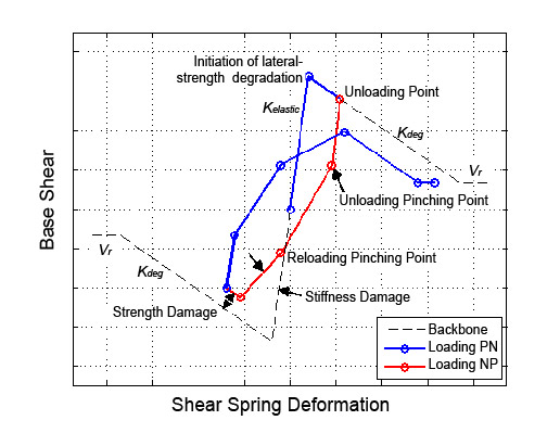
floating point unloading force pinching factor for loading in the negative direction
Note: This value must be between zero and unity
|
| $YpinchRPN |
floating point reloading force pinching factor for loading in the negative direction
Note: This value must be between negative one and unity
|
| $XpinchRPN |
floating point reloading displacement pinching factor for loading in the negative direction
Note: This value must be between negative one and unity
|
| $YpinchUNP |
floating point unloading force pinching factor for loading in the positive direction
Note: This value must be between zero and unity
|
| $YpinchRNP |
floating point reloading force pinching factor for loading in the positive direction
Note: This value must be between negative one and unity
|
| $XpinchRNP |
floating point reloading displacement pinching factor for loading in the positive direction
Note: This value must be between negative one and unity
|
| $dmgStrsLimE |
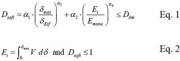
floating point force limit for elastic stiffness damage (typically defined as the lowest of shear strength or shear at flexrual yielding). This value is used to compute the maximum deformation at flexural yield (δmax Eq. 1) and using the initial elastic stiffness (Kelastic) the monotonic energy (Emono Eq. 1) to yield. Input 1 if this type of damage is not required and set $dmgE1, $dmgE2, $dmgE3, $dmgE4, and $dmgELim to zero
|
| $dmgDispMax |
floating point for ultimate drift at failure (δmax Eq. 1) and is used for strength and stiffness damage. This value is used to compute the monotonic energy at axial failure (Emono Eq. 2) by computing the area under the backbone in the positive loading direction up to δmax. Input 1 if this type of damage is not required and set $dmgR1, $dmgR2, $dmgR3, $dmgR4, and $dmgRLim to zero for reloading stiffness damage. Similarly set $dmgS1, $dmgS2, $dmgS3, $dmgS4, and $dmgSLim to zero if reloading strength damage is not required
|
| $dmgE1 $dmgE2 $dmgE3 $dmgE4 |
floating point elastic damage factors α1,α2,α3,α4 shown in Eq. 1
|
| $dmgELim |
floating point elastic damage limit Dlim shown in Eq. 1; Note: This value must be between zero and unity
|
| $dmgR1 $dmgR2 $dmgR3 $dmgR4 |
floating point reloading stiffness damage factors α1,α2,α3,α4 shown in Eq. 1
|
| $dmgRLim |
floating point reloading stiffness damage limit Dlim shown in Eq. 1; Note: This value must be between zero and unity
|
| $dmgRCyc |
floating point cyclic reloading stiffness damage index; Note: This value must be between zero and unity
|
| $dmgS1 $dmgS2 $dmgS3 $dmgS4 |
floating point strength damage factors α1,α2,α3,α4 shown in Eq. 1
|
| $dmgSLim |
floating point strength damage limit Dlim shown in Eq. 1; Note: This value must be between zero and unity
|
| $dmgSCyc |
floating point cyclic strength damage index; Note: This value must be between zero and unity
|
NOTES:


Damage Model Equations:
Elastic stiffness, reloading stiffness, and strength can be adjusted using the following energy and displacement damage model (from Mitra and Lowes (2007)):

EXAMPLE:
PinchingLimitStateMaterial Example
DESCRIPTION:
REFERENCES:
1. LeBorgne M. R., 2012, "Modeling the Post Shear Failure Behavior of Reinforced Concrete Columns." Austin, Texas: University of Texas at Austin, PhD, 301.
2. LeBorgne M. R. , Ghannoum W. M., 2013, "Analytical Element for Simulating Lateral-Strength Degradation in Reinforced Concrete Columns and Other Frame Members," Journal of Structural Engineering, V. doi: 10.1061/(ASCE)ST.1943-541X.0000925
3. Ghannoum W. M., Moehle J. P., 2012, "Rotation-Based Shear Failure Model for Lightly Confined Reinforced Concrete Columns," Journal of Structural Engineering, V. 138, No. 10, 1267-78.
4. Mitra Nilanjan, Lowes Laura N., 2007, "Evaluation, Calibration, and Verification of a Reinforced Concrete Beam--Column Joint Model," Journal of Structural Engineering, V. 133, No. 1, 105-20.
Code Developed by: Matthew Leborgne and Wassim M. Ghannoum, University of Texas at Austin
|


