PressureDependMultiYield03 Material: Difference between revisions
No edit summary |
No edit summary |
||
| (15 intermediate revisions by the same user not shown) | |||
| Line 1: | Line 1: | ||
{{CommandManualMenu}} | {{CommandManualMenu}} | ||
(The reference for '''PressureDependMultiYield03''' material: Khosravifar, A., Elgamal, A., Lu, J., and Li, J. [2018]. "A 3D model for earthquake-induced liquefaction triggering and post-liquefaction response." Soil Dynamics and Earthquake Engineering, 110, 43-52) | (The reference for '''PressureDependMultiYield03''' material: Khosravifar, A., Elgamal, A., Lu, J., and Li, J. [2018]. "A 3D model for earthquake-induced liquefaction triggering and post-liquefaction response." Soil Dynamics and Earthquake Engineering, 110, 43-52) | ||
'''PressureDependMultiYield03''' is modified from '''PressureDependMultiYield02''' material to comply with the established guidelines on the dependence of liquefaction triggering to the number of loading cycles, effective overburden stress (Kσ), and static shear stress (Kα). Element drivers for single element simulations under undrained cyclic, undrained monotonic, drained cyclic and drained monotonic loading can be downloaded from | '''PressureDependMultiYield03''' is modified from '''PressureDependMultiYield02''' material to comply with the established guidelines on the dependence of liquefaction triggering to the number of loading cycles, effective overburden stress (Kσ), and static shear stress (Kα). Element drivers for single element simulations under undrained cyclic, undrained monotonic, drained cyclic and drained monotonic loading can be [[PDMY03_elementdriver|downloaded from here]]. | ||
{| | {| | ||
| Line 35: | Line 33: | ||
''' | Table 1 provides the proposed calibrated input parameters for '''PressureDependMultiYield03''' for four different relative densities. Table 2 provides a brief description for each parameter and the adopted calibration procedure. | ||
Table 1. Model Input Parameters | |||
[[File:Pdmy03_table1.png]] | |||
'''*'''These are not input parameters to the constitutive model, but rather parameters computed during model calibration. | |||
Table 2. Description of Calibration Parameters | |||
[[File:Pdmy03_table2.png]] | |||
Latest revision as of 23:52, 10 June 2019
- Command_Manual
- Tcl Commands
- Modeling_Commands
- model
- uniaxialMaterial
- ndMaterial
- frictionModel
- section
- geometricTransf
- element
- node
- sp commands
- mp commands
- timeSeries
- pattern
- mass
- block commands
- region
- rayleigh
- Analysis Commands
- Output Commands
- Misc Commands
- DataBase Commands
(The reference for PressureDependMultiYield03 material: Khosravifar, A., Elgamal, A., Lu, J., and Li, J. [2018]. "A 3D model for earthquake-induced liquefaction triggering and post-liquefaction response." Soil Dynamics and Earthquake Engineering, 110, 43-52)
PressureDependMultiYield03 is modified from PressureDependMultiYield02 material to comply with the established guidelines on the dependence of liquefaction triggering to the number of loading cycles, effective overburden stress (Kσ), and static shear stress (Kα). Element drivers for single element simulations under undrained cyclic, undrained monotonic, drained cyclic and drained monotonic loading can be downloaded from here.
| nDMaterial PressureDependMultiYield03 $tag $nd $rho $refShearModul $refBulkModul $frictionAng $peakShearStra $refPress $pressDependCoe $PTAng $mType $ca $cb $cc $cd $ce $da $db $dc <$noYieldSurf=20 <$r1 $Gs1 …> $liquefac1=1. $liquefac2=0. $pa=101 <$s0=1.73>> |
| $ca, $cb, $cc, $cd, $ce | Non-negative constants defining the rate of contract or pore pressure buildup. See Tables 1 and 2 below for more information. |
| $da, $db, $dc | A non-negative constant reflecting Kσ effect. |
| $contrac2 | Non-negative constants defining the rate of dilation. See Tables 1 and 2 below for more information. |
| $mType | 0: Triaxial Compression; 1: Triaxial Extension; 2: Direct Shear |
| $s0 | Numerical constant (default value = 1.73 kPa). See Tables 1 and 2 below for more information. |
| Others | See PressureDependMultiYield02 material above and Tables 1 and 2 below. |
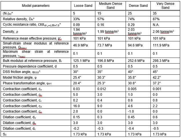
Table 1 provides the proposed calibrated input parameters for PressureDependMultiYield03 for four different relative densities. Table 2 provides a brief description for each parameter and the adopted calibration procedure.
Table 1. Model Input Parameters
*These are not input parameters to the constitutive model, but rather parameters computed during model calibration.
Table 2. Description of Calibration Parameters
Code Developed by: UC San Diego (Dr. Zhaohui Yang):
UC San Diego Soil Model:
- NDMaterial Command
- UC San Diego soil models (Linear/Nonlinear, dry/drained/undrained soil response under general 2D/3D static/cyclic loading conditions (please visit UCSD for examples)
- UC San Diego Saturated Undrained soil
- Element Command
- UC San Diego u-p element (saturated soil)
- Related References

