SelfCentering Material: Difference between revisions
(Created page with '{{CommandManualMenu}} This command is used to construct a uniaxial self-centering (flag-shaped) material object with optional non-recoverable slip behaviour and an optional stif...') |
No edit summary |
||
| (3 intermediate revisions by the same user not shown) | |||
| Line 8: | Line 8: | ||
| style="background:yellow; color:black; width:800px" | '''uniaxialMaterial SelfCentering $matTag $k1 $k2 $sigAct $beta <$epsSlip> <$epsBear> <rBear>''' | {| | ||
|style="background:yellow; color:black; width:800px" | '''uniaxialMaterial SelfCentering $matTag $k1 $k2 $sigAct $beta <$epsSlip> <$epsBear> <rBear>''' | |||
|} | |} | ||
| Line 33: | Line 34: | ||
: | [[Image:SC1.png]] | ||
[[Image:SC2.png]] | |||
[[Image:SC3.png]] | |||
[[Image: | [[Image:SC4.png]] | ||
[[Image:SC5.png]] | |||
[[Image: | [[Image:SC6.png]] | ||
[[Image:SC7.png]] | |||
---- | ---- | ||
Latest revision as of 21:48, 23 March 2010
- Command_Manual
- Tcl Commands
- Modeling_Commands
- model
- uniaxialMaterial
- ndMaterial
- frictionModel
- section
- geometricTransf
- element
- node
- sp commands
- mp commands
- timeSeries
- pattern
- mass
- block commands
- region
- rayleigh
- Analysis Commands
- Output Commands
- Misc Commands
- DataBase Commands
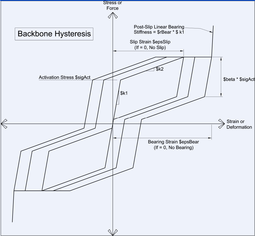
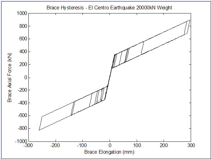
This command is used to construct a uniaxial self-centering (flag-shaped) material object with optional non-recoverable slip behaviour and an optional stiffness increase at high strains (bearing behaviour).
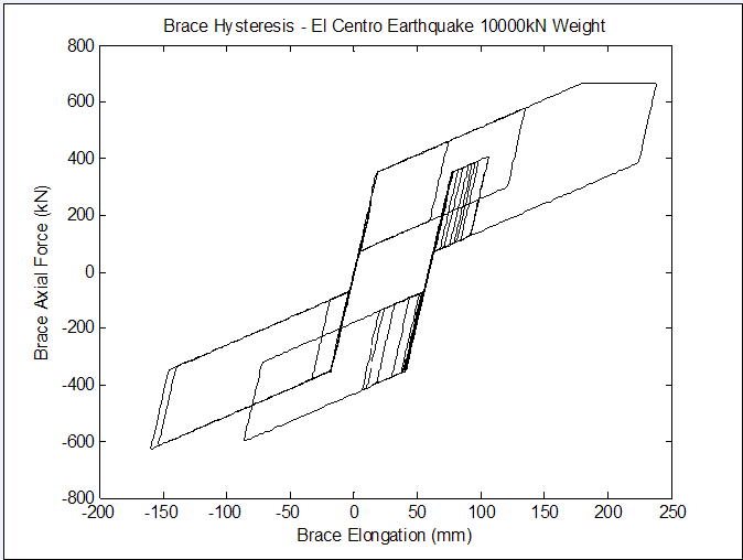
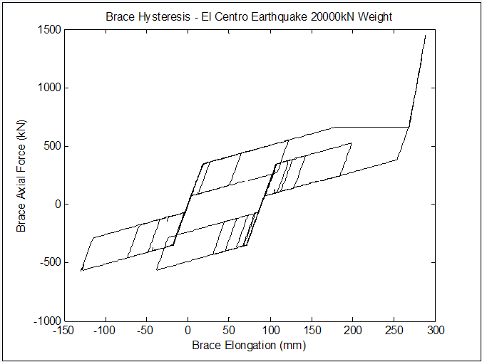
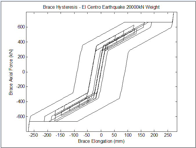
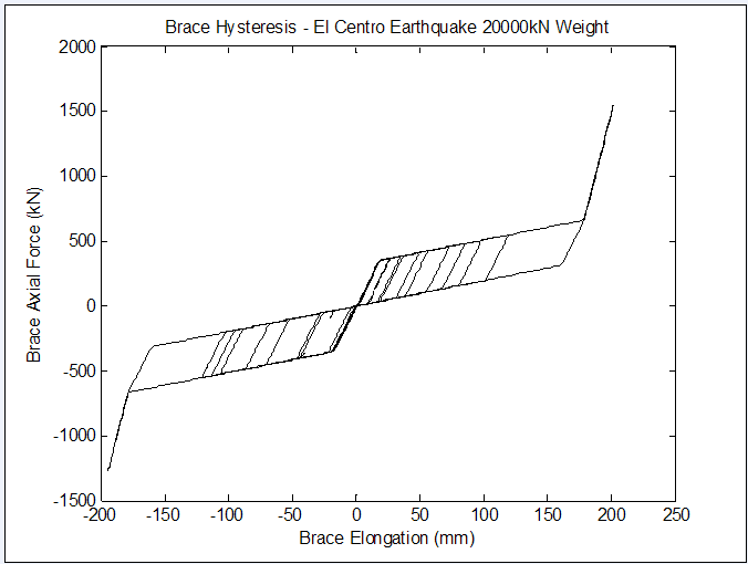
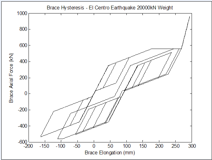
This material is primarily used to model a self-centering energy-dissipative (SCED) brace (Christopoulos et al., 2008) with the option to model the slippage of an external friction fuse (which causes non-recoverable deformation above a given brace strain). In practice, the external friction fuse is used to limit the amount of force in the brace (since the post-activation stiffness is generally non-zero). The bearing option is used to approximately model the effect of bolt bearing in the brace or external fuse mechanisms, which causes a steep increase in the stiffness of the brace. For self-centering energy-dissipative brace design, this bearing effect model may be used to impose a limit on slip or activation strain based on the anticipated available strain capacity of the mechanism. Note that this bearing effect is only intended to be a flag to indicate the existence of bearing; the SCED brace system should be designed such that the brace will not experience such bearing in practice.
This material type could potentially be used for any comparable self-centering system that exhibits a flag-shaped hysteretic response (for example: rocking wall systems if the uniaxial material is used as a moment/rotation hysteresis).
| uniaxialMaterial SelfCentering $matTag $k1 $k2 $sigAct $beta <$epsSlip> <$epsBear> <rBear> |
| $matTag | integer tag identifying material |
| $k1 | Initial Stiffness |
| $k2 | Post-Activation Stiffness (0<$k2<$k1) |
| $sigAct | Forward Activation Stress/Force |
| $beta | Ratio of Forward to Reverse Activation Stress/Force |
| $epsSlip | slip Strain/Deformation (if $epsSlip = 0, there will be no slippage) |
| $epsBear | Bearing Strain/Deformation (if $epsBear = 0, there will be no bearing) |
| $rBear | Ratio of Bearing Stiffness to Initial Stiffness $k1 |
REFERENCES:
Christopoulos, C., Tremblay, R., Kim, H.-J., and Lacerte, M. (2008). "Self-Centering Energy Dissipative Bracing System for the Seismic Resistance of Structures: Development and Validation" Journal of Structural Engineering ASCE, 134(1), 96-107.
Tremblay, R., Lacerte, M., and Christopoulos, C. (2008). "Seismic Response of Multistory Buildings with Self-Centering Energy Dissipative Steel Braces" Journal of Structural Engineering ASCE, 134(1), 108-120.
Code Developed by: Jeff Erochko, University of Toronto
