BuildingTclViewer Input Menu -- Elevation Model

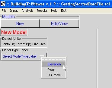
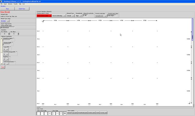
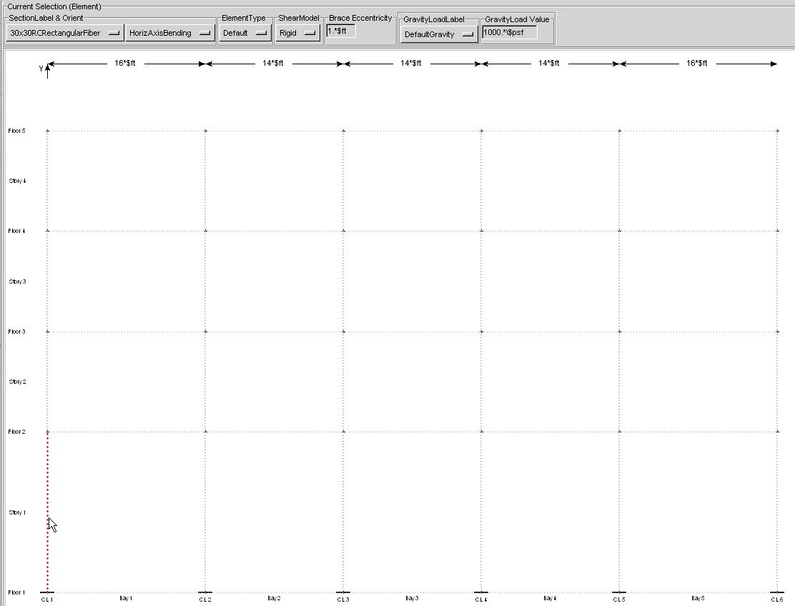
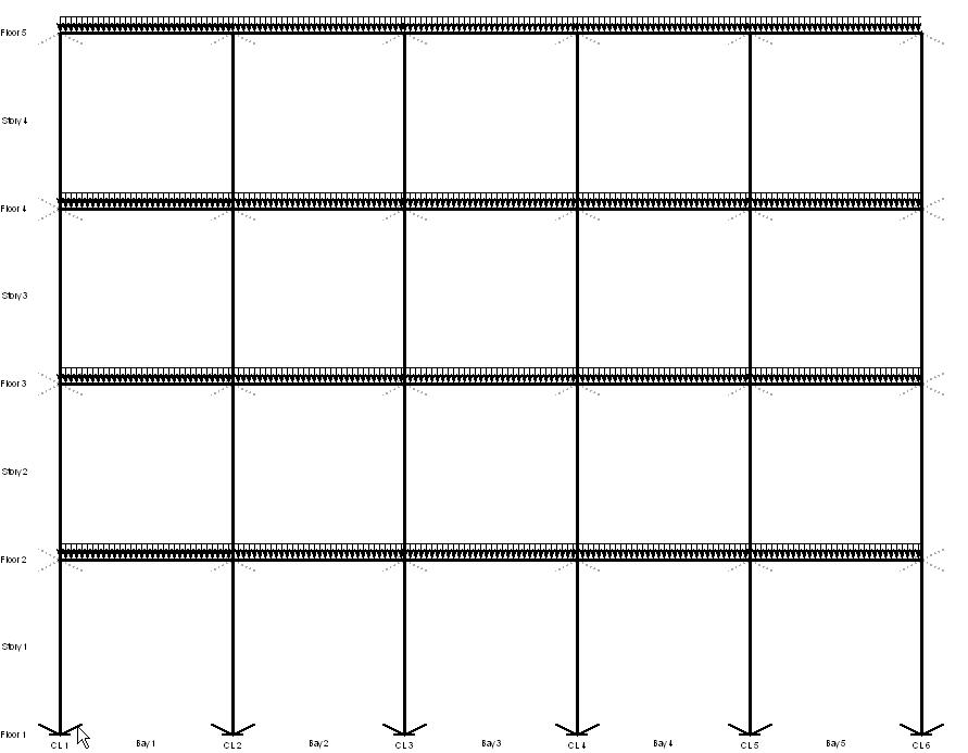
The Elevation input window starts as shown below:

Input Parameters
The model Required Arguments and Optional Arguments should be edited first.
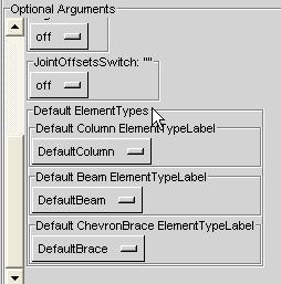
The Default ElementTypes are defined for each structural-element type (Beam, Column, Brace, etc.) and is used when the ElementType in the current-selection window above the elevation is left as "Default"
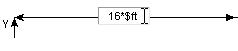
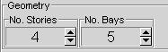
Geometry
The bay width and story height are modified directly on the dimension text. The number of stories and bays is controlled by the controls in the left menu. The bay width and story height of any additional stories and bays is set equal to the previous one. The user should follow these steps:
1. The first bay will be the bay on the bottom left of the elevation.
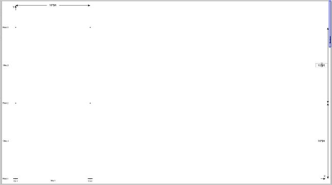
2. Manually modify the bay width and story height to the desired values.
- The program recalculates the values and redraws the picture to scale once the cursor leaves the text box. Therefore, do not exit the text box until the correct value is input. An error may result if this step is not done properly.

3. Increase the number of stories and bays iteratively with their heights and widths
Frame Elements and Gravity Loads
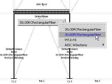
1. Set Current-selection properties:
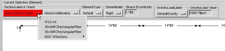
Once an element section has been selected all possible elements are diplayed. These possible elements are called ghost elements.
NOTE: If the ElementType button is left at "Default", the program will use the default element types corresponding to the structural element. The user may modify the default element type in the Optional Arguments window:
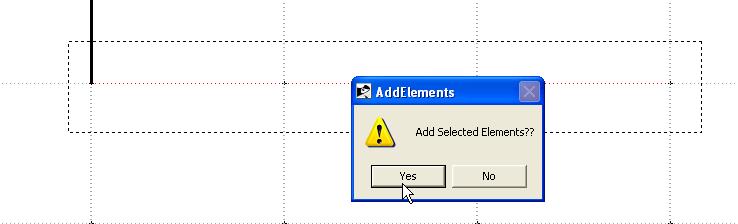
2.Assign the elements with the selected properties in the frame iteratively.
Initially, only columns and beams are possible.
The user defines an element or load by clicking the mouse button on a ghost, which becomes highlighter when the mouse passes over it.
NOTE: To select more than one ghost element, hold the shift key while creating a window which includes the entire ghost element (bottom-left to top right)
NOTE: To remove elements, click on an element while holding the control key
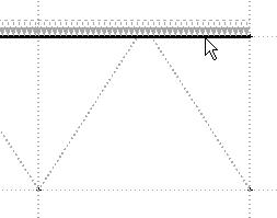
3. Chevron Braces & Gravity Loads -- Once a beam above a bay has been defined, ghost ChevronBraces and GravityLoads in that bay appear.
The user may now define those objects by selecting the corresponding SectionLabel and clicking on the ghost elements.
4. Column Hinges -- Once a column has been been defined and a SectionLabel whose SectionModelLabel=ColumnHinge has been selected, ghost ColumnHinges appear.

The user may now define those objects by clicking on the ghost elements.
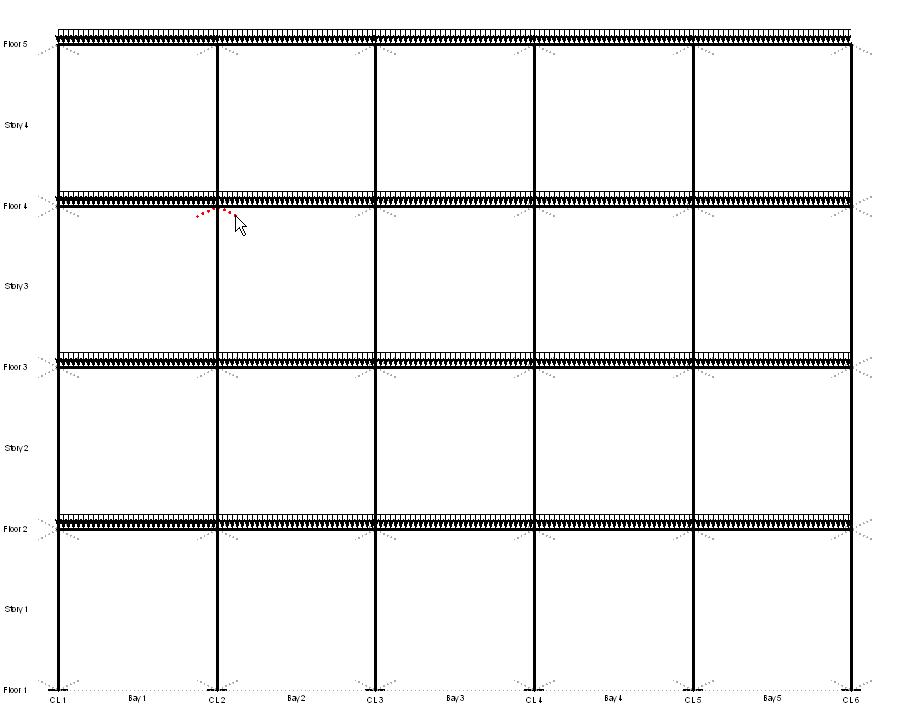
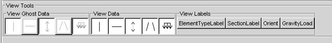
5. The View-Tools buttons below the elevation drawing allow the user to turn on and off ghost elements and gravity loads, defined elements and gravity loads, and element and gravity-load labels.

6. Once the labels are being displayed, the user may modify characteristics of an individual element or gravity load after it has been defined.
DO NOT FORGET TO SAVE.
For a new model, save the new data. For an existing model, either click the modify option, or the SaveAs.. option.
The current release lets the user exit the Model Input window without prompting and without saving any new input or modifications.