Excavation Supported by Cantilevered Sheet Pile Wall: Difference between revisions
No edit summary |
No edit summary |
||
| Line 41: | Line 41: | ||
The sheet pile wall is modeled using the [[Displacement-Based Beam-Column Element|displacement-based beam-column elements]] with [[Elastic Section|elastic sections]] used to define the constitutive behavior. The beam elements are placed along the neutral axis of the sheet pile wall, and to ensure the best behavior for the beam contact elements, the beam elements are defined such that their nodes are centered vertically between the nodes of the adjacent soil elements. | The sheet pile wall is modeled using the [[Displacement-Based Beam-Column Element|displacement-based beam-column elements]] with [[Elastic Section|elastic sections]] used to define the constitutive behavior. The beam elements are placed along the neutral axis of the sheet pile wall, and to ensure the best behavior for the beam contact elements, the beam elements are defined such that their nodes are centered vertically between the nodes of the adjacent soil elements. | ||
The beam-solid contact approach used in this example allows for the use of beam-column elements to model the sheet pile wall, enabling the results to be interpreted in the context of traditional beam theory, i.e. it is simple to extract shear and moment diagrams from the recorded data. Figs. 3 and 4 show the types of visualizations that can be realized using this approach in concert with GiD, showing the evolution of the bending moment and shear force demands in the sheet pile wall during the excavation. | |||
[[File:momentDiagram.gif|frame|Fig. 3: Animated moment diagram for excavation analysis.]] | |||
[[File:momentDiagram.gif|frame|Fig. 4: Animated shear diagram for excavation analysis.]] | |||
<br style="clear: both" /> | <br style="clear: both" /> | ||
| Line 49: | Line 55: | ||
[[File:finalContact.png|frame|Fig. 4: Contact forces in final excavated configuration.]] | [[File:finalContact.png|frame|Fig. 4: Contact forces in final excavated configuration.]] | ||
The interface between the sheet pile wall and the surrounding soil domain is defined using [[BeamContact2D|two-dimensional beam-solid contact elements]]. | The interface between the sheet pile wall and the surrounding soil domain is defined using [[BeamContact2D|two-dimensional beam-solid contact elements]]. These elements accept the thickness of the wall as an input parameter, this thickness is manifested as the gap between the beam and solid elements. The [[BeamContact2D]] elements link two master nodes (from the beam element), to a slave node (from adjacent soil element), and work best when the initial position of the slave node is nearly centered vertically between the two beam nodes, though this node need only be between the beam nodes for the contact to be maintained. These elements use Lagrange multipliers to enforce the contact condition, therefore an additional node is required. In the example input file, the Lagrange multiplier nodes are numbered 1001 to 1042 and are clearly labeled with comments. | ||
The constitutive behavior of the interface is defined using the [[ContactMaterial2D]] nDMaterial object. This constitutive model uses a regularized Coulomb frictional law allowing for sticking and frictional slip. | |||
The beam-solid elements provide the ability to determine and visualize the contact forces acting on the interface. Examples of the visualizations possible for these elements are shown in Figs. 3 and 4, which show the contact state after the completion of the initial state analysis, and after the completion of the excavation, respectively. | |||
[[File:contactForces.gif|frame|Fig. 12: Animated contact forces for excavation analysis.]] | |||
=== Recorders === | === Recorders === | ||
| Line 81: | Line 93: | ||
<br style="clear: both" /> | <br style="clear: both" /> | ||
<br style="clear: both" /> | <br style="clear: both" /> | ||
[[OpenSees User| Return to OpenSees User Page]] | [[OpenSees User| Return to OpenSees User Page]] | ||
Revision as of 01:22, 5 March 2011
Example prepared by: Christopher McGann and Pedro Arduino, University of Washington
This article describes the simulation of an excavation supported by a cantilevered sheet pile wall using OpenSees. The model considers plane strain conditions in two-dimensions, using quadrilateral elements with a pressure dependent constitutive model to simulate cohesionless soil, and beam-column elements to simulate a unit width of sheet pile wall. Beam-solid contact elements are used to model a frictional interface between the linear beam elements and the quadrilateral soil elements.
The input file used for this example is available to view and/or download here.
The pre- and post-process visualization tool GiD was used to generate this example. Further information on how GiD can be used for geotechnical simulations in OpenSees can be found in previous practical examples posted on this wiki. The GiD tool can be downloaded from http://gid.cimne.upc.es/download.
Model Description
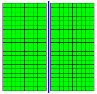

The analysis described in this example uses the finite element mesh shown in Fig. 1. The soil domain is 10 m tall and 10.5 m wide. The sheet pile wall considered in this example is 0.5 m wide and has a height of 10.5 m. Beam contact elements are used to create a frictional interface between the beam and solid elements that accounts for the full kinematics of the beam elements and allows the constant width of the wall to be represented in the model. The gap between the blue beam elements and the green solid elements in Fig. 1 is the representation of the 0.5 m width of the wall made possible by the contact elements.
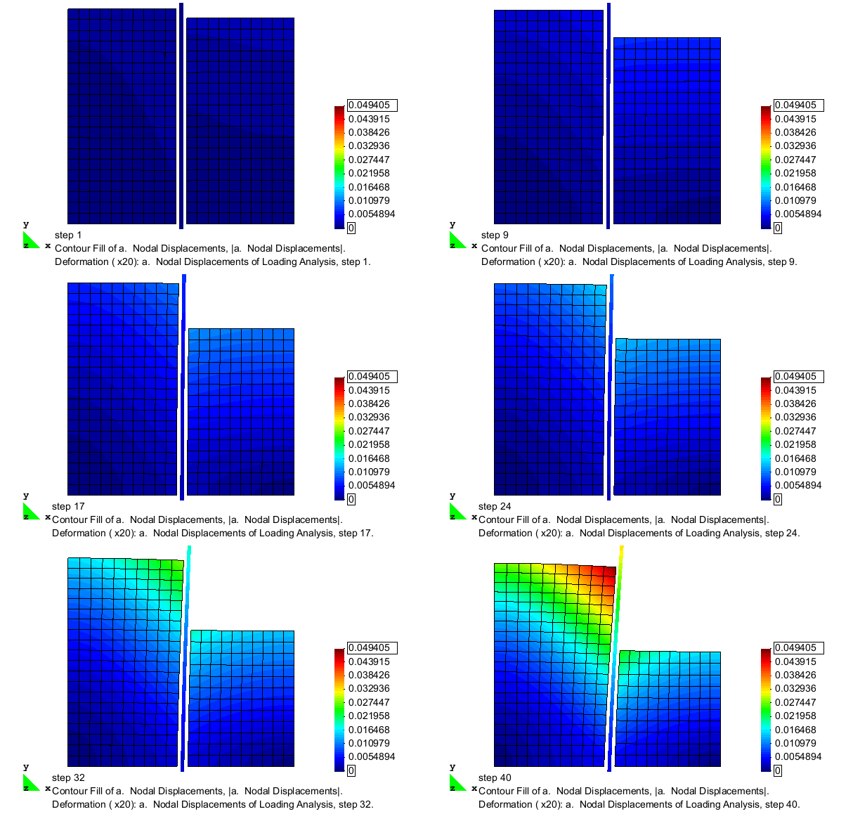
The excavation is simulated by incrementally removing layers of solid elements from one side of the sheet pile wall. After each removal, the model is analyzed for a sufficient number of steps such that equilibrium is reached prior to the removal of the next layer of elements. The removal process continues until an excavation depth of 5 m is achieved. The deformed configuration of the mesh after the completion of the excavation analysis is shown in Fig. 2. As shown, the removal of material from one side of the sheet pile wall allows the wall to be pushed laterally by the remaining soil on the other side. In this figure, the displacement magnitudes are magnified 25 times in order to clearly display the deformation pattern.
Boundary Conditions
The boundary conditions for this model are relatively simple. The nodes for the solid elements, created with two translational degrees of freedom, are fixed against lateral translation on the left and right hand boundaries, and fixed against vertical translation along the lower boundary. The remaining solid element nodes are left free. The lateral extents of the soil domain were set at ten times the wall thickness on either side of the wall-soil interface to reduce unwanted boundary effects.
The nodes for the beam elements, created with three degrees of freedom (two translational, one rotational), are all left free with the exception of the node at the base of the wall, which is fixed against vertical translation only.
Material and Element Definitions
The model used in this excavation analysis contains three types of elements, solid quadrilateral elements for the soil domain, displacement-based beam elements for the sheet pile wall, and beam contact elements to define the frictional wall-soil interface. Three constitutive models (one per element type) are used to define the material behavior of the various components in this model.
Soil Elements and Material
Four-node quad elements are used to model the soil using the plane strain formulation of the quad element. The element connectivity uses a counterclockwise pattern for these elements. A unit thickness is defined for these elements, indicating that the soil domain in this plane strain model represents a 1 m thick slice of a three-dimensional soil domain. The self-weight of the soil is considered as a body force acting on each element with a magnitude equal to the soil unit weight.
This example considers a homogenous soil domain, therefore, a single constitutive model is used for the soil elements. The PressureDependMultiYield02 nDMaterial object is used for this example, representing a cohesionless soil.
Sheet Pile Wall
The sheet pile wall is modeled using the displacement-based beam-column elements with elastic sections used to define the constitutive behavior. The beam elements are placed along the neutral axis of the sheet pile wall, and to ensure the best behavior for the beam contact elements, the beam elements are defined such that their nodes are centered vertically between the nodes of the adjacent soil elements.
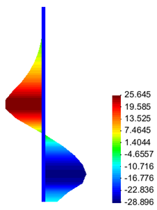
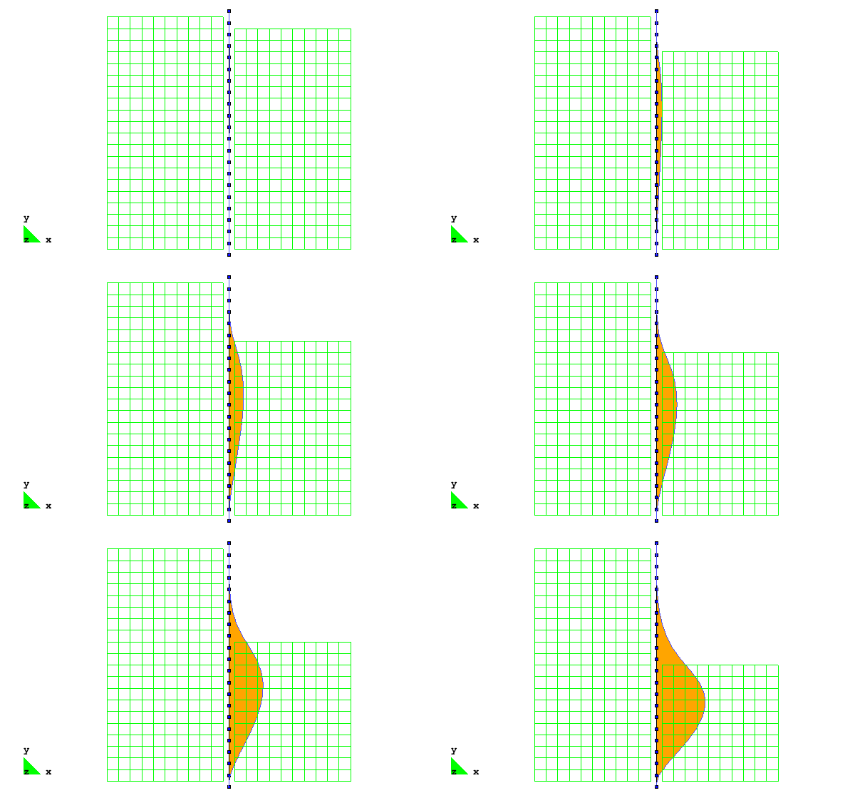
The beam-solid contact approach used in this example allows for the use of beam-column elements to model the sheet pile wall, enabling the results to be interpreted in the context of traditional beam theory, i.e. it is simple to extract shear and moment diagrams from the recorded data. Figs. 3 and 4 show the types of visualizations that can be realized using this approach in concert with GiD, showing the evolution of the bending moment and shear force demands in the sheet pile wall during the excavation.

Soil-Wall Interface

The interface between the sheet pile wall and the surrounding soil domain is defined using two-dimensional beam-solid contact elements. These elements accept the thickness of the wall as an input parameter, this thickness is manifested as the gap between the beam and solid elements. The BeamContact2D elements link two master nodes (from the beam element), to a slave node (from adjacent soil element), and work best when the initial position of the slave node is nearly centered vertically between the two beam nodes, though this node need only be between the beam nodes for the contact to be maintained. These elements use Lagrange multipliers to enforce the contact condition, therefore an additional node is required. In the example input file, the Lagrange multiplier nodes are numbered 1001 to 1042 and are clearly labeled with comments.
The constitutive behavior of the interface is defined using the ContactMaterial2D nDMaterial object. This constitutive model uses a regularized Coulomb frictional law allowing for sticking and frictional slip.
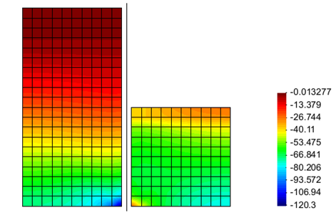
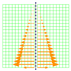
The beam-solid elements provide the ability to determine and visualize the contact forces acting on the interface. Examples of the visualizations possible for these elements are shown in Figs. 3 and 4, which show the contact state after the completion of the initial state analysis, and after the completion of the excavation, respectively.

Recorders
Initial State Analysis Phase
Excavation Analysis Phase
Representative Results

