Effective Stress Site Response Analysis of a Layered Soil Column: Difference between revisions
No edit summary |
No edit summary |
||
| Line 29: | Line 29: | ||
[[File:siteRespSlopeModel.png|frame|Fig 1. Layered soil profile modeled by the example discussed in this article.]] | [[File:siteRespSlopeModel.png|frame|Fig 1. Layered soil profile modeled by the example discussed in this article.]] | ||
== Analysis Results == | |||
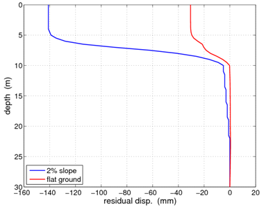
[[File:effDepthSummary.png|frame|Fig 2. Comparison of residual displacements for flat ground and a 2% grade after the conclusion of the excitation.]] | [[File:effDepthSummary.png|frame|Fig 2. Comparison of residual displacements for flat ground and a 2% grade after the conclusion of the excitation.]] | ||
| Line 36: | Line 38: | ||
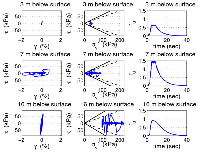
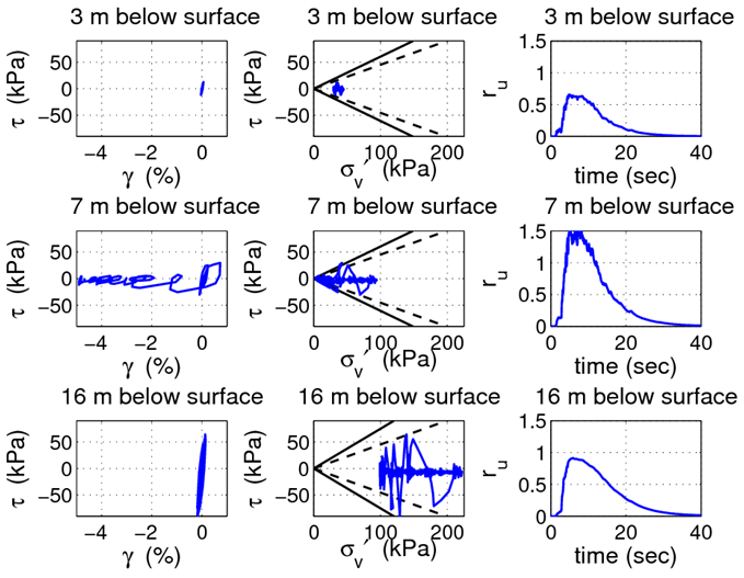
[[File:slopeSummary.png|frame|Fig 4. Summary of stress, strain, and excess pore pressure response for three depths in the sloping ground analysis.]] | [[File:slopeSummary.png|frame|Fig 4. Summary of stress, strain, and excess pore pressure response for three depths in the sloping ground analysis.]] | ||
== GiD Visualization == | |||
[http://opensees.berkeley.edu/wiki/images/d/d4/FlatAnimation.gif response animation] | [http://opensees.berkeley.edu/wiki/images/d/d4/FlatAnimation.gif response animation] | ||
Revision as of 20:39, 1 October 2010
Example posted by: Christopher McGann, University of Washington
!!!!UNDER CONSTRUCTION!!!!
This article describes the OpenSees implementation of an effective stress site response analysis of a layered deposit of cohesionless soil underlain by an elastic half-space. A single column of soil is modeled in 2D (with periodic boundary conditions to emulate a 1D analysis) and is subject to an earthquake excitation. Nine node quadrilateral elements with both displacement and pore pressure degrees of freedom enable the model to track changes in pore pressure and effective stress during the earthquake excitation. A Lysmer-Kuhlemeyer (1969) dashpot is utilized to account for the finite rigidity of the underlying elastic medium.
This article also briefly introduces the user to the pre- and post-process visualization tool GiD. Specifically, the means to generate GiD-compatible results from the data returned by the OpenSees recorders are provided and discussed. GiD is a powerful tool for visualizing data and generating meshes, among other things. It is especially helpful when working with 2D and 3D problems in OpenSees. The GiD tool can be downloaded from http://gid.cimne.upc.es/download.
Note: Most of the details of this analysis are identical to those in the Total Stress Site Response Analysis of a Layered Soil Column example posted in the Practical Examples area of this manual. This article will emphasize the attributes which are particular to the effective stress analysis. The user is referred to the total stress example for further information on details which may be omitted or quickly explained here.
Provided with this article are several files. Files which are required for the analysis are indicated. The files include:
- The example input file, freeFieldEffective.tcl (required for analysis)
- The velocity time history of the selected earthquake record, velocityHistory.out (required for analysis)
- A GiD post-process mesh file, freeFieldEffective.flavia.msh (generated automatically by running freeFieldEffective.tcl)
- A Matlab script, flaviaWriter.m, which can be used to reformat the recorded displacement, pore pressure, and stress data into a file which can be read by GiD for post-process visulization. Non-Matlab users may find the process represented by this file useful in creating an alternative means for accomplishing this reformatting.
- The post-process results file, freeFieldEffective.flavia.res, which is generated through the use of the flaviaWriter.m script. This file, combined with the file freeFieldEffective.flavia.msh, allows the user to visualize the results of the site response analysis using GiD.
All of the files mentioned above can be downloaded by clicking here.
To run this example, the user must download the input file, freeFieldEffective.tcl, and the velocity time history file, velocityHistory.out, and place them in a single directory. Once this has been done, the user can then run the analysis. The additional files described above are not essential to the analysis. They are provided to demonstrate how to use the GiD tool to visualize results from this type of analysis.
For further information into a site response analysis using OpenSees, the user is referred to the previously-mentioned total stress site response analysis example and/or the large set of examples developed at the University of California at San Diego available at http://cyclic.ucsd.edu/opensees. These examples utilize a wide variety of element and material formulations, as well as different boundary and loading conditions than those used in this example.
Model Description
Analysis Results


