OpenSees Example 9. Build & Analyze a Section Example: Difference between revisions
No edit summary |
No edit summary |
||
| Line 19: | Line 19: | ||
:::2. In the 3D model, torsional stiffness needs to be aggregated to the section | :::2. In the 3D model, torsional stiffness needs to be aggregated to the section | ||
{| style="margin:0; background:none;" | |||
<!-- Column 1 --> | <!-- Column 1 --> | ||
|- | | style="margin:0; width:25%; border:3px solid #ccc; background:#white; vertical-align:top; " | | ||
| style=" | {| style="width:100%; vertical-align:top;background:#white;" | ||
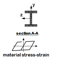
<h4>Uniaxial Section</h4> | <h4>Uniaxial Section</h4> | ||
---- | ---- | ||
|- | |||
| style="color:#000;" | | |||
[[File:ExampleFigure_FiberSection_W.GIF|link=OpenSees Example 8. generic 3D Frame, NStory NBayX NBayZ, Reinforced-Concrete Section & Steel W-Section]] | |||
|} | |||
<!-- Column 2 --> | |||
| style="margin:0; width:25%; border:3px solid #ccc; background:#white; vertical-align:top; " | | |||
{| style="width:100%; vertical-align:top;background:#white;" | |||
<strong>Files</strong> | <strong>Files</strong> | ||
*[[Media:Ex9a.build.UniaxialSection2D.tcl|Ex9a.build.UniaxialSection2D.tcl]] | *[[Media:Ex9a.build.UniaxialSection2D.tcl|Ex9a.build.UniaxialSection2D.tcl]] | ||
*[[Media:Ex9a.build.UniaxialSection3D.tcl| | *[[Media:Ex9a.build.UniaxialSection3D.tcl|Ex9a.build.UniaxialSection3D.tcl]] | ||
*[[Media:LibUnits.tcl|LibUnits.tcl]] | *[[Media:LibUnits.tcl|LibUnits.tcl]] | ||
---- | |} | ||
<!-- Column 3 --> | |||
| style="margin:0; width:25%; border:3px solid #ccc; background:#white; vertical-align:top; " | | |||
{| style="width:100%; vertical-align:top;background:#white;" | |||
<strong>Notes</strong> | <strong>Notes</strong> | ||
*Flexure and axial behavior are uncoupled in this type of section | *Flexure and axial behavior are uncoupled in this type of section | ||
|} | |} | ||
|} | |||
| Line 49: | Line 63: | ||
{| style="width:100%; border:1px solid #ddcef2; vertical-align:top;background:#white;" | {| style="width:100%; border:1px solid #ddcef2; vertical-align:top;background:#white;" | ||
|- | |- | ||
| style="color:#000;" | | | style="color:#000;" | | ||
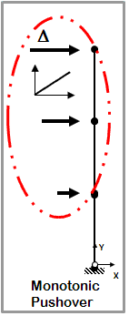
<h5>Static Pushover</h5> | <h5>Static Pushover</h5> | ||
[[File:ExampleFigure_Push.GIF|link=OpenSees Example 9. Build & Analyze a Section Example]] | [[File:ExampleFigure_Push.GIF|link=OpenSees Example 9. Build & Analyze a Section Example]] | ||
| Line 59: | Line 73: | ||
<strong>Notes</strong> | <strong>Notes</strong> | ||
*One-directional monotonic displacement-controlled static loading | *One-directional monotonic displacement-controlled static loading | ||
|} | |} | ||
---- | ---- | ||
{| style="width:100%; border:1px solid #ddcef2; vertical-align:top;background:#white;" | {| style="width:100%; border:1px solid #ddcef2; vertical-align:top;background:#white;" | ||
|- | |- | ||
| style="color:#000;" | | | style="color:#000;" | | ||
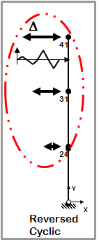
<h5>Static Reversed Cyclic</h5> | <h5>Static Reversed Cyclic</h5> | ||
[[File:ExampleFigure_Cyclic.GIF|link=OpenSees Example 9. Build & Analyze a Section Example]] | [[File:ExampleFigure_Cyclic.GIF|link=OpenSees Example 9. Build & Analyze a Section Example]] | ||
| Line 76: | Line 90: | ||
*One-directional displacement-controlled static loading | *One-directional displacement-controlled static loading | ||
*Displacement cycles are imposed in positive and negative direction | *Displacement cycles are imposed in positive and negative direction | ||
|} | |} | ||
| Line 84: | Line 98: | ||
{| style="width:100%; border:1px solid #ddcef2; vertical-align:top;background:#white;" | {| style="width:100%; border:1px solid #ddcef2; vertical-align:top;background:#white;" | ||
|- | |- | ||
| style="color:#000;" | | | style="color:#000;" | | ||
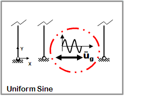
<h5>Dynamic Uniform Sine-Wave Ground Motion</h5> | <h5>Dynamic Uniform Sine-Wave Ground Motion</h5> | ||
[[File:ExampleFigure_UniformSine.GIF|link=OpenSees Example 9. Build & Analyze a Section Example]] | [[File:ExampleFigure_UniformSine.GIF|link=OpenSees Example 9. Build & Analyze a Section Example]] | ||
| Line 95: | Line 109: | ||
*Sine-wave acceleration input | *Sine-wave acceleration input | ||
*Same acceleration input at all nodes restrained in specified direction | *Same acceleration input at all nodes restrained in specified direction | ||
|} | |} | ||
---- | ---- | ||
{| style="width:100%; border:1px solid #ddcef2; vertical-align:top;background:#white;" | {| style="width:100%; border:1px solid #ddcef2; vertical-align:top;background:#white;" | ||
|- | |- | ||
| style="color:#000;" | | | style="color:#000;" | | ||
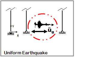
<h5>Dynamic Uniform Earthquake Ground Motion (typical)</h5> | <h5>Dynamic Uniform Earthquake Ground Motion (typical)</h5> | ||
[[File:ExampleFigure_UniformEQ.GIF|link=OpenSees Example 9. Build & Analyze a Section Example]] | [[File:ExampleFigure_UniformEQ.GIF|link=OpenSees Example 9. Build & Analyze a Section Example]] | ||
| Line 113: | Line 127: | ||
*Earthquake (from file) acceleration input | *Earthquake (from file) acceleration input | ||
*Same acceleration input at all nodes restrained in specified direction | *Same acceleration input at all nodes restrained in specified direction | ||
|} | |} | ||
---- | ---- | ||
{| style="width:100%; border:1px solid #ddcef2; vertical-align:top;background:#white;" | {| style="width:100%; border:1px solid #ddcef2; vertical-align:top;background:#white;" | ||
|- | |- | ||
| style="color:#000;" | | | style="color:#000;" | | ||
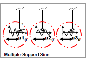
<h5>Dynamic Multiple-Support Sine-Wave Ground Motion</h5> | <h5>Dynamic Multiple-Support Sine-Wave Ground Motion</h5> | ||
[[File:ExampleFigure_MultiSupportSine.GIF|link=OpenSees Example 9. Build & Analyze a Section Example]] | [[File:ExampleFigure_MultiSupportSine.GIF|link=OpenSees Example 9. Build & Analyze a Section Example]] | ||
| Line 129: | Line 143: | ||
*Sine-wave displacement input | *Sine-wave displacement input | ||
*Different displacements are specified at particular nodes in specified directions | *Different displacements are specified at particular nodes in specified directions | ||
|} | |} | ||
---- | ---- | ||
{| style="width:100%; border:1px solid #ddcef2; vertical-align:top;background:#white;" | {| style="width:100%; border:1px solid #ddcef2; vertical-align:top;background:#white;" | ||
|- | |- | ||
| style="color:#000;" | | | style="color:#000;" | | ||
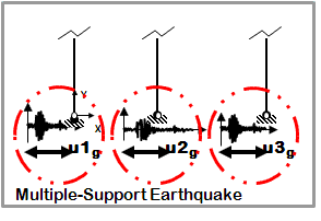
<h5>Dynamic Multiple-Support Earthquake Ground Motion</h5> | <h5>Dynamic Multiple-Support Earthquake Ground Motion</h5> | ||
[[File:ExampleFigure_MultiSupportEQ.GIF|link=OpenSees Example 9. Build & Analyze a Section Example]] | [[File:ExampleFigure_MultiSupportEQ.GIF|link=OpenSees Example 9. Build & Analyze a Section Example]] | ||
| Line 147: | Line 161: | ||
*Earthquake (from file) displacement input | *Earthquake (from file) displacement input | ||
*Different displacements are specified at particular nodes in specified directions | *Different displacements are specified at particular nodes in specified directions | ||
|} | |} | ||
---- | ---- | ||
{| style="width:100%; border:1px solid #ddcef2; vertical-align:top;background:#white;" | {| style="width:100%; border:1px solid #ddcef2; vertical-align:top;background:#white;" | ||
|- | |- | ||
| style="color:#000;" | | | style="color:#000;" | | ||
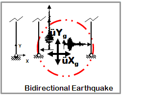
<h5>Dynamic Bidirectional Earthquake Ground Motion (typical)</h5> | <h5>Dynamic Bidirectional Earthquake Ground Motion (typical)</h5> | ||
[[File:ExampleFigure_BidirectEQ.GIF|link=OpenSees Example 9. Build & Analyze a Section Example]] | [[File:ExampleFigure_BidirectEQ.GIF|link=OpenSees Example 9. Build & Analyze a Section Example]] | ||
| Line 167: | Line 181: | ||
*Different ground motion in two directions | *Different ground motion in two directions | ||
*Same acceleration input at all nodes restrained in specified direction | *Same acceleration input at all nodes restrained in specified direction | ||
|} | |} | ||
Revision as of 22:08, 11 November 2009
Introduction
For the case of the uniaxial section, moment-curvature and axial force-deformation curves are defined independently, and numerically.
For the case of the fiber sections (steel and RC), uniaxial materials are defined numerically (stress-strain relationship) and are combined into a fiber section where moment-curvature and axial force-deformation characteristics and their interaction are calculated computationally.
Input
Model Building
- 2D vs. 3D
- While this distinction does not affect the section definition itself, it affects the degree-of-freedom associated with moment and curvature in the subsequent analysis.
- There are two differences between the two models:
- 1. The space defined with the model command (# Define the model builder, ndm=#dimension, ndf=#dofs)
- 2D
- model BasicBuilder -ndm 2 -ndf 3;
- 3D
- model BasicBuilder -ndm 3 -ndf 6;
- 2. In the 3D model, torsional stiffness needs to be aggregated to the section
- 1. The space defined with the model command (# Define the model builder, ndm=#dimension, ndf=#dofs)
Uniaxial Section |
Files |
Notes
|
Lateral-Load Analysis
The following tasks are performed in the analysis
- define lateral-load parameters
- analyze
Static
|
Dynamic EQ Ground Motion
|
Run
The model and analysis combinations for this example are numerous. The following are an small subset, for demonstration purposes:
- To run W-Section Model, Static Pushover Analysis:
puts " -------------Elastic Model -------------"
puts " -------------Static Pushover Analysis -------------"
source Ex8.genericFrame3D.build.Wsec.tcl
source Ex8.genericFrame3D.analyze.Static.Push.tcl
- To run RC Model, Uniform Earthquake Excitation
puts " -------------Uniaxial Inelastic Section, Nonlinear Model -------------"
puts " -------------Uniform Earthquake Excitation -------------"
source Ex8.genericFrame3D.build.RCsec.tcl
source Ex8.genericFrame3D.analyze.Dynamic.EQ.Uniform.tcl
Notes
In this example, the following items are variables:
- Number of stories in Y direction
- Number of bays in X direction
- Number of bays in Z direction
- Elastic/Fiber Section
- Display: none/node numbering/deformed shape/mode shape (can choose which mode) (variable display scaling factor for both the deformed shape and the mode shape, this scaling factor is dependent on the user choice)
Return to OpenSees Examples Manual -- Structural Models & Analyses
Return to OpenSees User
