OpenSees Example 7. 3D Frame, 3-story 3-bayX 3-bayZ, Reinforced-Concrete Section & Steel W-Section: Difference between revisions
Jump to navigation
Jump to search
No edit summary |
No edit summary |
||
| Line 1: | Line 1: | ||
==Introduction== | ==Introduction== | ||
This example is the first example in a 3D space. | *This example is the first example in a 3D space. | ||
The frame in this examples is a 3-story, 3-bay frame in both directions. | *The frame in this examples is a 3-story, 3-bay frame in both directions. | ||
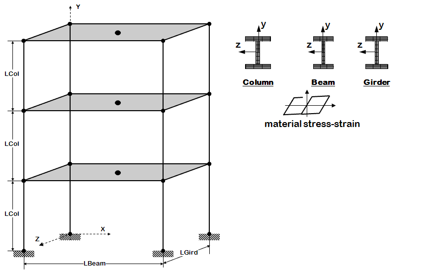
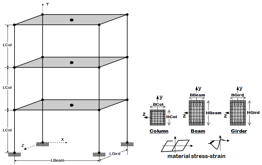
The columns (elements parallel to Y-direction), beams (elements parallel to X-direction), and girders (elements parallel to Z-direction), are all defined at the section level, one section of each of these types of elements. | *The columns (elements parallel to Y-direction), beams (elements parallel to X-direction), and girders (elements parallel to Z-direction), are all defined at the section level, one section of each of these types of elements. | ||
The sections can either be elastic sections (useful to check elastic properties) or fiber sections. | *The sections can either be elastic sections (useful to check elastic properties) or fiber sections. | ||
As in the previous frame examples, both reinforced-concrete and steel W-sections are demonstrated in this example. | *As in the previous frame examples, both reinforced-concrete and steel W-sections are demonstrated in this example. | ||
As is shown in this example, the reinforced-concrete model using the nonlinearBeamColumn element has difficulties converging at very large lateral deformations. | *As is shown in this example, the reinforced-concrete model using the nonlinearBeamColumn element has difficulties converging at very large lateral deformations. | ||
A second model is, therefore, included in this example, which uses the Opensees [[Beam With Hinges Element]] element to model the columns. This element is able to achieve convergence at such high lateral-drift levels. | *A second model is, therefore, included in this example, which uses the Opensees [[Beam With Hinges Element]] element to model the columns. This element is able to achieve convergence at such high lateral-drift levels. | ||
This example also demonstrates the use of pre-packaged display procedures. (The current OpenSees display features are limited as their development was halted early on) | *This example also demonstrates the use of pre-packaged display procedures. (The current OpenSees display features are limited as their development was halted early on) | ||
==Input== | ==Input== | ||
<h3>Model Building</h3> | <h3>Model Building</h3> | ||
The following tasks are performed when building the model | *The following tasks are performed when building the model | ||
<blockquote> | <blockquote> | ||
*define units | *define units | ||
| Line 19: | Line 18: | ||
*define & apply gravity | *define & apply gravity | ||
</blockquote> | </blockquote> | ||
*The only difference between the two input files is in modelling the element section properties and calculating beam and column weight/mass. | |||
{| style="margin:0; background:none;" | {| style="margin:0; background:none;" | ||
| Line 24: | Line 24: | ||
| style="margin:0; width:25%; border:3px solid #ccc; background:#white; vertical-align:top; " | | | style="margin:0; width:25%; border:3px solid #ccc; background:#white; vertical-align:top; " | | ||
{| style="width:100%; vertical-align:top;background:#white;" | {| style="width:100%; vertical-align:top;background:#white;" | ||
<h4> | <h4>Steel W Section</h4> | ||
---- | ---- | ||
|- | |- | ||
| style="color:#000;" | <div> | | style="color:#000;" | <div> | ||
[[File: | [[File:Example7_W.GIF|link=OpenSees Example 7. 3D Frame, 3-story 3-bayX 3-bayZ, Reinforced-Concrete Section & Steel W-Section]] | ||
---- | ---- | ||
<strong>Files</strong> | <strong>Files</strong> | ||
*[[Media:Ex7.Frame3D.build. | *[[Media:Ex7.Frame3D.build.Wsec.tcl|Ex7.Frame3D.build.Wsec.tcl]] | ||
*[[Media:LibUnits.tcl|LibUnits.tcl]] | *[[Media:LibUnits.tcl|LibUnits.tcl]] | ||
*[[Media:Wsection.tcl|Wsection.tcl]] | |||
*[[Media:DisplayPlane.tcl|DisplayPlane.tcl]] | *[[Media:DisplayPlane.tcl|DisplayPlane.tcl]] | ||
*[[Media:DisplayModel3D.tcl|DisplayModel3D.tcl]] | *[[Media:DisplayModel3D.tcl|DisplayModel3D.tcl]] | ||
---- | ---- | ||
<strong>Notes</strong> | <strong>Notes</strong> | ||
* | *3D building frame: Steel W sections for both columns and beams. (variable elastic or fiber section) | ||
</div> | </div> | ||
|} | |} | ||
| Line 44: | Line 44: | ||
| style="margin:0; width:25%; border:3px solid #ccc; background:#white; vertical-align:top; " | | | style="margin:0; width:25%; border:3px solid #ccc; background:#white; vertical-align:top; " | | ||
{| style="width:100%; vertical-align:top;background:#white;" | {| style="width:100%; vertical-align:top;background:#white;" | ||
<h4> | <h4>RC Section</h4> | ||
---- | ---- | ||
|- | |- | ||
| style="color:#000;" | <div> | | style="color:#000;" | <div> | ||
[[File: | [[File:Example7_RC.GIF|link=OpenSees Example 7. 3D Frame, 3-story 3-bayX 3-bayZ, Reinforced-Concrete Section & Steel W-Section]] | ||
---- | ---- | ||
<strong>Files</strong> | <strong>Files</strong> | ||
*[[Media:Ex7.Frame3D.build. | *[[Media:Ex7.Frame3D.build.RCsec.tcl|Ex7.Frame3D.build.RCsec.tcl]] | ||
*[[Media:LibUnits.tcl|LibUnits.tcl]] | *[[Media:LibUnits.tcl|LibUnits.tcl]] | ||
*[[Media:LibMaterialsRC.tcl|LibMaterialsRC.tcl]] | *[[Media:LibMaterialsRC.tcl|LibMaterialsRC.tcl]] | ||
| Line 103: | Line 59: | ||
---- | ---- | ||
<strong>Notes</strong> | <strong>Notes</strong> | ||
* | *3D building frame: Reinforced-concrete rectangular sections for both columns and beams. (variable elastic or fiber section) | ||
</div> | </div> | ||
|} | |} | ||
|} | |} | ||
| Line 250: | Line 205: | ||
The model and analysis combinations for this example are numerous. The following are an small subset, for demonstration purposes: | The model and analysis combinations for this example are numerous. The following are an small subset, for demonstration purposes: | ||
* To run | * To run W-Section Model, Static Pushover Analysis: | ||
<blockquote><source lang="Tcl"> | <blockquote><source lang="Tcl"> | ||
puts " -------------Elastic Model -------------" | puts " -------------Elastic Model -------------" | ||
puts " -------------Static Pushover Analysis -------------" | puts " -------------Static Pushover Analysis -------------" | ||
source Ex7.Frame3D.build. | source Ex7.Frame3D.build.Wsec.tcl | ||
source Ex7.Frame3D.analyze.Static.Push.tcl | source Ex7.Frame3D.analyze.Static.Push.tcl | ||
</source></blockquote> | </source></blockquote> | ||
* To run | * To run RC Model, Uniform Earthquake Excitation | ||
<blockquote><source lang="Tcl"> | <blockquote><source lang="Tcl"> | ||
puts " -------------Uniaxial Inelastic Section, Nonlinear Model -------------" | puts " -------------Uniaxial Inelastic Section, Nonlinear Model -------------" | ||
puts " -------------Uniform Earthquake Excitation -------------" | puts " -------------Uniform Earthquake Excitation -------------" | ||
source Ex7.Frame3D.build. | source Ex7.Frame3D.build.RCsec.tcl | ||
source Ex7.Frame3D.analyze.Dynamic.EQ.Uniform.tcl | source Ex7.Frame3D.analyze.Dynamic.EQ.Uniform.tcl | ||
</source></blockquote> | </source></blockquote> | ||
==Notes== | ==Notes== | ||
Revision as of 21:32, 11 November 2009
Introduction
- This example is the first example in a 3D space.
- The frame in this examples is a 3-story, 3-bay frame in both directions.
- The columns (elements parallel to Y-direction), beams (elements parallel to X-direction), and girders (elements parallel to Z-direction), are all defined at the section level, one section of each of these types of elements.
- The sections can either be elastic sections (useful to check elastic properties) or fiber sections.
- As in the previous frame examples, both reinforced-concrete and steel W-sections are demonstrated in this example.
- As is shown in this example, the reinforced-concrete model using the nonlinearBeamColumn element has difficulties converging at very large lateral deformations.
- A second model is, therefore, included in this example, which uses the Opensees Beam With Hinges Element element to model the columns. This element is able to achieve convergence at such high lateral-drift levels.
- This example also demonstrates the use of pre-packaged display procedures. (The current OpenSees display features are limited as their development was halted early on)
Input
Model Building
- The following tasks are performed when building the model
- define units
- define model
- define recorders for output
- define & apply gravity
- The only difference between the two input files is in modelling the element section properties and calculating beam and column weight/mass.
Steel W Section
|
RC Section
|
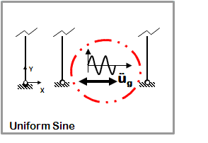
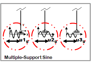
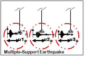
Lateral-Load Analysis
The following tasks are performed in the analysis
- define lateral-load parameters
- analyze
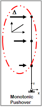
Static
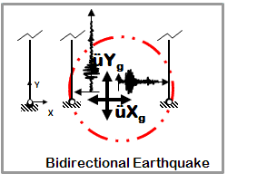
|
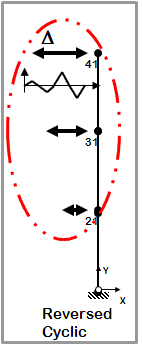
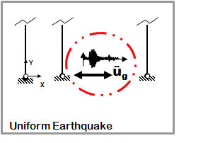
Dynamic EQ Ground Motion
|
Run
The model and analysis combinations for this example are numerous. The following are an small subset, for demonstration purposes:
- To run W-Section Model, Static Pushover Analysis:
puts " -------------Elastic Model -------------"
puts " -------------Static Pushover Analysis -------------"
source Ex7.Frame3D.build.Wsec.tcl
source Ex7.Frame3D.analyze.Static.Push.tcl
- To run RC Model, Uniform Earthquake Excitation
puts " -------------Uniaxial Inelastic Section, Nonlinear Model -------------"
puts " -------------Uniform Earthquake Excitation -------------"
source Ex7.Frame3D.build.RCsec.tcl
source Ex7.Frame3D.analyze.Dynamic.EQ.Uniform.tcl
Notes
Return to OpenSees Examples Manual -- Structural Models & Analyses
Return to OpenSees User
