Excavation Supported by Cantilevered Sheet Pile Wall: Difference between revisions
Jump to navigation
Jump to search
(Created page with 'Example prepared by: <span style="color:blue"> Christopher McGann and Pedro Arduino, University of Washington</span> ---- Return to OpenSees User Page This ...') |
No edit summary |
||
| Line 14: | Line 14: | ||
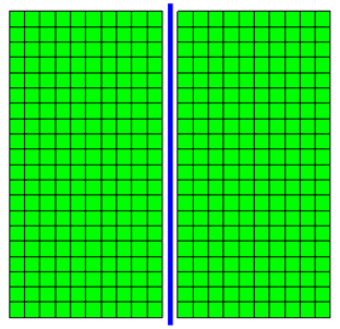
[[File:originalMesh.png|frame|Fig. 1: Undeformed FE mesh for the excavation model.]] | [[File:originalMesh.png|frame|Fig. 1: Undeformed FE mesh for the excavation model.]] | ||
[[File:excavatedMesh.png|frame|Fig. 2: Deformed FE mesh after completion of excavation.]] | |||
=== Boundary Conditions === | === Boundary Conditions === | ||
=== Material and Element Definitions === | === Material and Element Definitions === | ||
==== Soil ==== | |||
==== Sheet Pile Wall ==== | |||
==== Soil-Wall Interface ==== | |||
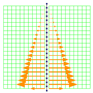
[[File:initialContact.png|frame|Fig. 3: Contact forces after completion of initial state analysis.]] | |||
[[File:finalContact.png|frame|Fig. 4: Contact forces in final excavated configuration.]] | |||
=== Recorders === | === Recorders === | ||
== Results == | === Initial State Analysis Phase === | ||
=== Excavation Analysis Phase === | |||
== Representative Results == | |||
[[File:.png|frame|Fig. 5: ]] | |||
[[File:.png|frame|Fig. 6: ]] | |||
[[File:.png|frame|Fig. 7: ]] | |||
[[OpenSees User| Return to OpenSees User Page]] | |||
Revision as of 22:09, 4 March 2011
Example prepared by: Christopher McGann and Pedro Arduino, University of Washington
This article describes the simulation of an excavation supported by a cantilevered sheet pile wall using OpenSees. The model considers plane strain conditions in two-dimensions, using quadrilateral elements with a pressure dependent constitutive model to simulate cohesionless soil, and beam-column elements to simulate a unit width of sheet pile wall. Beam-solid contact elements are used to model a frictional interface between the linear beam elements and the quadrilateral soil elements.
The input file used for this example is available to view and/or download here.
Model Description


Boundary Conditions
Material and Element Definitions
Soil
Sheet Pile Wall
Soil-Wall Interface

