Line 9:
Line 9: The following types of models are represented in these examples:
The following types of models are represented in these examples:
;*Elastic
;*<h2> Elastic</h2>
: OpenSees [[Elastic Beam Column Element]]
: OpenSees [[Elastic Beam Column Element]]
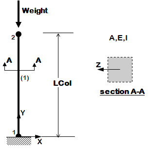
: The elastic, uncoupled, axial and flexural stiffnesses are defined at the element level
: The elastic, uncoupled, axial and flexural stiffnesses are defined at the element level
: user specifies: E,I,A
: user specifies: E,I,A
;*Inelastic Elements
;*<h2> Inelastic Elements/<h2>
: OpenSees [[Force-Based Beam-Column Element]]
: OpenSees [[Force-Based Beam-Column Element]]
: Two types of sections
: Two types of sections
::*Uniaxial Section
::*<h3> Uniaxial Section</h3>
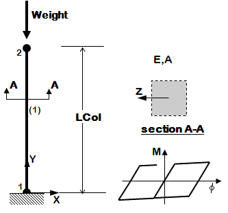
::: The inelastic, uncoupled, axial and flexural stiffnesses are defined at the section level
::: The inelastic, uncoupled, axial and flexural stiffnesses are defined at the section level
::: The OpenSees [[Uniaxial Section]] Command is used
::: The OpenSees [[Uniaxial Section]] Command is used
Line 22:
Line 22: :::: Axial stiffness A
:::: Axial stiffness A
:::: Section Moment-Curvature characteristics via the OpenSees [[UniaxialMaterial Command]]
:::: Section Moment-Curvature characteristics via the OpenSees [[UniaxialMaterial Command]]
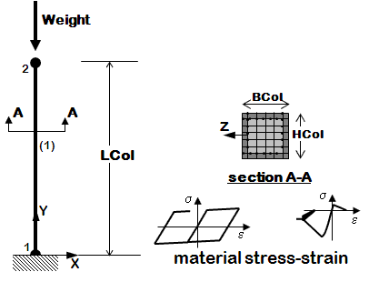
::*Fiber Section
::*<h3> Fiber Section</h3>
::: The section is broken down into fibers where uniaxial materials are defined independently.
::: The section is broken down into fibers where uniaxial materials are defined independently.
::: The program calculates the coupled flexural and axial stiffnesses/strength by integrating strains across the section
::: The program calculates the coupled flexural and axial stiffnesses/strength by integrating strains across the section
Revision as of 21:07, 11 November 2009
Introduction The following examples are listed in order of simplicity.
NOTE: gravity analysis is always included as part of the model building
Models The following types of models are represented in these examples:
OpenSees Elastic Beam Column Element
The elastic, uncoupled, axial and flexural stiffnesses are defined at the element level
user specifies: E,I,A OpenSees Force-Based Beam-Column Element
Two types of sections
The inelastic, uncoupled, axial and flexural stiffnesses are defined at the section level
The OpenSees Uniaxial Section Command is used
User specifies:
Axial stiffness A
Section Moment-Curvature characteristics via the OpenSees UniaxialMaterial Command The section is broken down into fibers where uniaxial materials are defined independently.
The program calculates the coupled flexural and axial stiffnesses/strength by integrating strains across the section
The OpenSees Fiber Section Command is used
User specifies
Stress-Strain characteristics via the OpenSees UniaxialMaterial Command for all number of materials
Section geometry via series of Patches and Layers in the fiber section
Two Section Geometries are presented
*RC Rectangular Section
*Standard AISC W section Lateral Loads The following types of lateral loads are represented in these examples:
Control node is located at the highest floor
Lateral-load distribution is proportional the the mass distribution along the height of the building
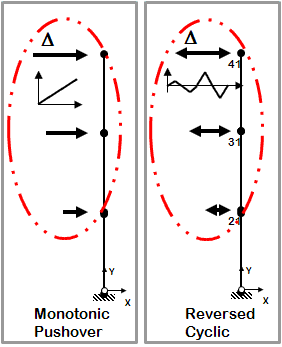
Static analysis
Two types
One-directional displacement-controlled static lateral loading One-directional displacement-controlled static lateral loading
Displacement cycles are imposed in positive and negative direction Time-Dependent Dynamic Loads Transient analysis
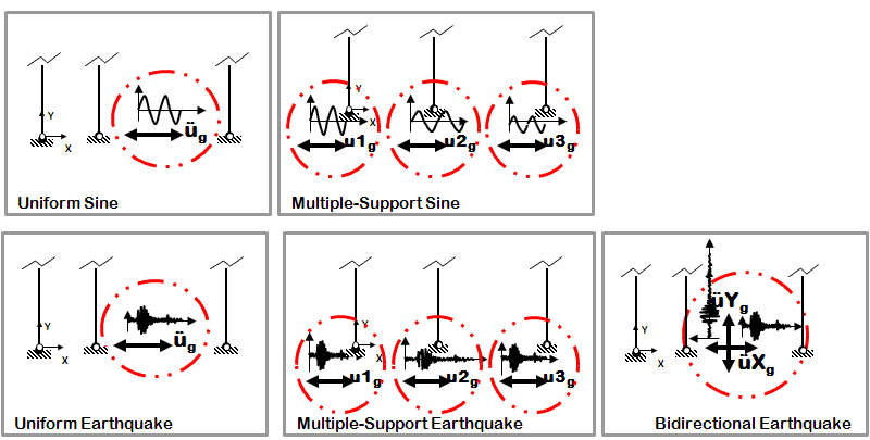
Four types
Sine-wave acceleration input
Same acceleration input at all nodes restrained in specified direction Multiple-Support Sine-Wave Sine-wave displacement input
Different displacements are specified at particular nodes in specified directions Earthquake (from file) acceleration input
Same acceleration input at all nodes restrained in specified direction Multiple-Support Earthquake Earthquake (from file) displacement input
Different displacements are specified at particular nodes in specified direction Different inputs are specified for two directions
Same acceleration input at all nodes restrained in specified direction Simulation Process Each example script does the following:
model dimensions and degrees-of-freedom
nodal coordinates
nodal constraints -- boundary conditions
nodal masses
elements and element connectivity
recorders for output B. Define & apply gravity load
nodal or element load
static-analysis parameters (tolerances & load increments)
analyze
hold gravity loads constant
reset time to zero C. Define and apply lateral load
load pattern (nodal loads for static analysis, support ground motion for earthquake)
lateral-analysis parameters (tolerances & displacement/time increments)
Static Lateral-Load Analysis
define the displacement increments and displacement path
Dynamic Lateral-Load Analysis
define the input motion and all associated parameters, such as scaling and input type
define analysis duration and time increment
define damping
analyze
Introductory Examples The objective of Example 1a and Example 1b is to give an overview of input-file format in OpenSees using simple scripts.
Objectives
overview of basic OpenSees input structure
coordinates, boundary conditions, element connectivity, nodal masses, nodal loads, etc.
two-node, one element
Analyses
static pushover
dynamic earthquake-input
Objectives
two element types
distributed element loads
Analyses
static pushover
dynamic earthquake-input
Simple Nonlinear Analysis Examples
Objectives
introduce variable: define & use
Analyses
static pushover
dynamic earthquake-input
Objectives
first example of nonlinear model, set nonlinearity at section level
Models
nonlinearBeamColumn element
uniaxial section
Analyses
static pushover
dynamic earthquake-input
Objectives
set nonlinearity at material level
material stress-strain response is assembled into fiber section
reinforced-concrete fiber section
Models
nonlinearBeamColumn element
uniaxial material
fiber section (Reinforced-concrete fiber section)
Analyses
static pushover
dynamic earthquake-input
2D Structural Modeling & Analysis Examples These examples take advantage of the Tcl scripting language starting from simple variable substitutions in the initial examples, to the more advanced techniques of array management and logical expressions (if-then statements).
Objectives
units, defined and used (they will be used in all subsequent examples)
separate model-building and analysis files
introduce PDelta effects (or not)
Models
elastic elements
inelastic uniaxial section
fiber section (Reinforced-concrete fiber section)
Linear, PDelta or Corotational Transformation
Analyses
static pushover
dynamic earthquake-input
Objectives
use previously-defined procedures to simplify input
introduce more analysis types
introduce procedure to read database input motion files (data with text in first lines)
Models
elastic elements
inelastic uniaxial section
inelastic fiber section (Reinforced-concrete fiber section)
Analyses
static reversed cyclic analysis
dynamic sine-wave input analysis (uniform excitation)
dynamic earthquake-input analysis (uniform excitation)
dynamic sine-wave input analysis (multiple-support excitation)
dynamic earthquake-input analysis (multiple-support excitation)
dynamic bidirectional earthquake-input analysis (uniform excitation)
Objectives
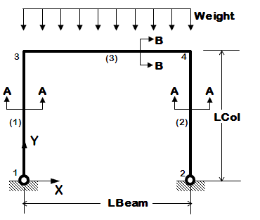
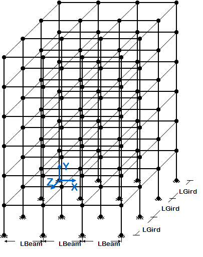
2D frame of fixed geometry: 3-story, 3-bay
nodes and elements are defined manually, one by one
Models
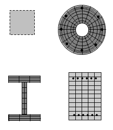
Reinforced-Concrete Section
Steel W-Section
elastic uniaxial section
inelastic uniaxial section
inelastic fiber section
Analyses
static reversed cyclic analysis
dynamic sine-wave input analysis (uniform excitation)
dynamic earthquake-input analysis (uniform excitation)
dynamic sine-wave input analysis (multiple-support excitation)
dynamic earthquake-input analysis (multiple-support excitation)
dynamic bidirectional earthquake-input analysis (uniform excitation)
Objectives
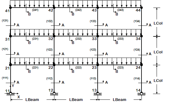
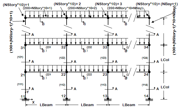
2D frame geometry of variable geometry ( # stories and # bays are variables)
node and element definition is automated
use previously-defined procedures to view model node numbers and elements, deformed shape, and displacement history, in 2D
Models
Reinforced-Concrete Section
Steel W-Section
elastic uniaxial section
inelastic uniaxial section
inelastic fiber section
Analyses
static reversed cyclic analysis
dynamic sine-wave input analysis (uniform excitation)
dynamic earthquake-input analysis (uniform excitation)
dynamic sine-wave input analysis (multiple-support excitation)
dynamic earthquake-input analysis (multiple-support excitation)
dynamic bidirectional earthquake-input analysis (uniform excitation)
3D Structural Modeling & Analysis Examples
A few items are new in 3D:
Additional coordinates need to be considered in defining nodes
Additional degrees of freedom need to be considered in defining the following:
nodal constraints (boundary conditions)
nodal masses
nodal loads
The transformation from local element/section coordinates to global system coordinates needs to be specified
Element loads are specified in local coordinates
Additional arguments are required for many elements (bending about local-y axis) properties
Element/Section torsional stiffness needs to be considered
Rigid floor diaphragms need be included for building models
Objectives
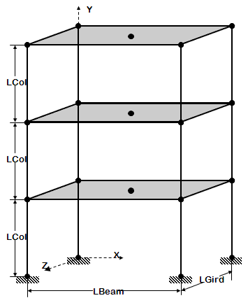
3D frame of fixed geometry
nodes and elements are manually manually, one by one
introduce rigid floor diaphragm
use previously-defined procedures to view model node numbers and elements, deformed shape, and displacement history, in 3D
Models
Reinforced-Concrete Section
Steel W-Section
Elastic or Fiber Section option is a variable within one input file
rigid diaphragm
Analyses
static reversed cyclic analysis
dynamic sine-wave input analysis (uniform excitation)
dynamic earthquake-input analysis (uniform excitation)
dynamic sine-wave input analysis (multiple-support excitation)
dynamic earthquake-input analysis (multiple-support excitation)
dynamic bidirectional earthquake-input analysis (uniform excitation)
Objectives
3D frame geometry of variable geometry ( # stories and # bays in X and Z are variables)
node and element definition is automated
introduce user-input interface, the user is given the option as to what to view in model
Models
Reinforced-Concrete Section
Steel W-Section
Elastic or Fiber Section option is a variable within one input file
optional rigid diaphragm
Analyses
static reversed cyclic analysis
dynamic sine-wave input analysis (uniform excitation)
dynamic earthquake-input analysis (uniform excitation)
dynamic sine-wave input analysis (multiple-support excitation)
dynamic earthquake-input analysis (multiple-support excitation)
dynamic bidirectional earthquake-input analysis (uniform excitation)
Section Modeling And Analysis Examples
Objectives
defined section using uniaxial behavior (define moment-curvature curve) or
define section using uniaxial materials (define stress-strain curve) in fiber section
Models
Uniaxial Nonlinear section
Fiber Steel W-section
Fiber RC symmetric rectangular unconfined-concrete section
Fiber RC symmetric rectangular unconfined & confined-concrete section
Fiber RC generalized rectangular section
Fiber RC generalized circular section
Analyses
2D static unidirectional moment-curvature analysis
3D static unidirectional moment-curvature analysis
Return to OpenSees User