OpenSees Example 9. Build & Analyze a Section Example: Difference between revisions
Jump to navigation
Jump to search
No edit summary |
No edit summary |
||
| (8 intermediate revisions by 2 users not shown) | |||
| Line 9: | Line 9: | ||
==Input== | ==Input== | ||
<h3>Model Building</h3> | <h3>Model Building</h3> | ||
:2D vs. 3D | :*2D vs. 3D | ||
::While this distinction does not affect the section definition itself, it affects the degree-of-freedom associated with moment and curvature in the subsequent analysis. | ::While this distinction does not affect the section definition itself, it affects the degree-of-freedom associated with moment and curvature in the subsequent analysis. | ||
::There are two differences between the two models: | ::There are two differences between the two models: | ||
| Line 21: | Line 21: | ||
{| style="margin:0; background:none; border:3px solid #ccc;" | |||
<!-- Column 1 --> | <!-- Column 1 --> | ||
| style="margin:0; width:25%; background:#white; vertical-align:top; " | | | style="margin:0; width:25%; background:#white; vertical-align:top; " | | ||
| Line 28: | Line 28: | ||
|- | |- | ||
| style="color:#000;" | | | style="color:#000;" | | ||
[[File: | [[File:ExampleSection_Uniaxial.GIF|link=OpenSees Example 9. Build & Analyze a Section Example]] | ||
|} | |} | ||
<!-- Column 2 --> | <!-- Column 2 --> | ||
| Line 53: | Line 53: | ||
|- | |- | ||
| style="color:#000;" | | | style="color:#000;" | | ||
[[File: | [[File:ExampleSection_W.GIF|link=OpenSees Example 9. Build & Analyze a Section Example]] | ||
|} | |} | ||
<!-- Column 2 --> | <!-- Column 2 --> | ||
| Line 78: | Line 78: | ||
|- | |- | ||
| style="color:#000;" | | | style="color:#000;" | | ||
[[File: | [[File:ExampleSection_RCSymmUnconf.GIF|link=OpenSees Example 9. Build & Analyze a Section Example]] | ||
|} | |} | ||
<!-- Column 2 --> | <!-- Column 2 --> | ||
| Line 84: | Line 84: | ||
{| style="width:100%; vertical-align:top;background:#white;" | {| style="width:100%; vertical-align:top;background:#white;" | ||
<strong>Files</strong> | <strong>Files</strong> | ||
*[[Media:Ex9c.build.RectUnconfinedSymm2D.tcl|Ex9c.build.RectUnconfinedSymm2D.tcl]] | *[[Media:Ex9c.build.RCSection.RectUnconfinedSymm2D.tcl|Ex9c.build.RCSection.RectUnconfinedSymm2D.tcl]] | ||
*[[Media:Ex9c.build.RectUnconfinedSymm3D.tcl|Ex9c.RectUnconfinedSymm3D | *[[Media:Ex9c.build.RCSection.RectUnconfinedSymm3D.tcl|Ex9c.build.RCSection.RectUnconfinedSymm3D.tcl]] | ||
*[[Media:LibUnits.tcl|LibUnits.tcl]] | *[[Media:LibUnits.tcl|LibUnits.tcl]] | ||
|} | |} | ||
| Line 103: | Line 103: | ||
|- | |- | ||
| style="color:#000;" | | | style="color:#000;" | | ||
[[File: | [[File:ExampleSection_RCSymmConf.GIF|link=OpenSees Example 9. Build & Analyze a Section Example]] | ||
|} | |} | ||
<!-- Column 2 --> | <!-- Column 2 --> | ||
| Line 109: | Line 109: | ||
{| style="width:100%; vertical-align:top;background:#white;" | {| style="width:100%; vertical-align:top;background:#white;" | ||
<strong>Files</strong> | <strong>Files</strong> | ||
*[[Media:Ex9d.build. | *[[Media:Ex9d.build.RCSection.RectConfinedSymm2D.tcl|Ex9d.build.RCSection.RectConfinedSymm2D.tcl]] | ||
*[[Media:Ex9d.build. | *[[Media:Ex9d.build.RCSection.RectConfinedSymm3D.tcl|Ex9d.build.RCSection.RectConfinedSymm3D.tcl]] | ||
*[[Media:LibUnits.tcl|LibUnits.tcl]] | *[[Media:LibUnits.tcl|LibUnits.tcl]] | ||
|} | |} | ||
| Line 128: | Line 128: | ||
|- | |- | ||
| style="color:#000;" | | | style="color:#000;" | | ||
[[File: | [[File:ExampleSection_RCrect.GIF|link=OpenSees Example 9. Build & Analyze a Section Example]] | ||
|} | |} | ||
<!-- Column 2 --> | <!-- Column 2 --> | ||
| Line 134: | Line 134: | ||
{| style="width:100%; vertical-align:top;background:#white;" | {| style="width:100%; vertical-align:top;background:#white;" | ||
<strong>Files</strong> | <strong>Files</strong> | ||
*[[Media:Ex9e.build.Rect2D.tcl|Ex9e.build.Rect2D.tcl]] | *[[Media:Ex9e.build.RCSection.Rect2D.tcl|Ex9e.build.RCSection.Rect2D.tcl]] | ||
*[[Media:Ex9e.build.Rect3D.tcl|Ex9e.build.Rect3D.tcl]] | *[[Media:Ex9e.build.RCSection.Rect3D.tcl|Ex9e.build.RCSection.Rect3D.tcl]] | ||
*[[Media:LibUnits.tcl|LibUnits.tcl]] | *[[Media:LibUnits.tcl|LibUnits.tcl]] | ||
|} | |} | ||
| Line 154: | Line 154: | ||
|- | |- | ||
| style="color:#000;" | | | style="color:#000;" | | ||
[[File: | [[File:ExampleSection_RCcirc.GIF|link=OpenSees Example 9. Build & Analyze a Section Example]] | ||
|} | |} | ||
<!-- Column 2 --> | <!-- Column 2 --> | ||
| Line 160: | Line 160: | ||
{| style="width:100%; vertical-align:top;background:#white;" | {| style="width:100%; vertical-align:top;background:#white;" | ||
<strong>Files</strong> | <strong>Files</strong> | ||
*[[Media:Ex9f.build.Circ2D.tcl|Ex9f.build.Circ2D.tcl]] | *[[Media:Ex9f.build.RCSection.Circ2D.tcl|Ex9f.build.RCSection.Circ2D.tcl]] | ||
*[[Media:Ex9f.build.Circ3D.tcl|Ex9f.build.Circ3D.tcl]] | *[[Media:Ex9f.build.RCSection.Circ3D.tcl|Ex9f.build.RCSection.Circ3D.tcl]] | ||
*[[Media:LibUnits.tcl|LibUnits.tcl]] | *[[Media:LibUnits.tcl|LibUnits.tcl]] | ||
|} | |} | ||
| Line 173: | Line 173: | ||
|} | |} | ||
{| style="margin:0; background:none; border:3px solid #ccc;" | |||
{| style="margin:0; background:none;" | |||
<!-- Column 1 --> | <!-- Column 1 --> | ||
| style="margin:0; width:25%; | | style="margin:0; width:25%; background:#white; vertical-align:top; " | | ||
{| style="width:100%; vertical-align:top;background:#white;" | |||
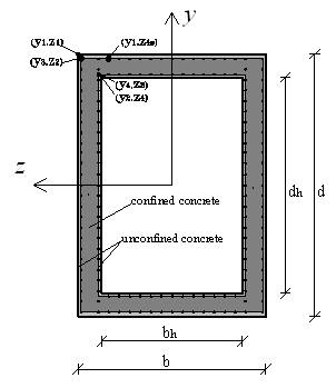
{| style="width:100% | <h4>Fiber Section: Reinforced Concrete Hollow Section -- Symmetric Section, Confined Concrete</h4> | ||
|- | |- | ||
| style="color:#000;" | | | style="color:#000;" | | ||
[[File:hollowRC.PNG|link=OpenSees Example 9. Build & Analyze a Section Example]] | |||
[[File: | |} | ||
---- | <!-- Column 2 --> | ||
| style="margin:0; width:25%; background:#white; vertical-align:top; " | | |||
{| style="width:100%; vertical-align:top;background:#white;" | |||
<strong>Files</strong> | <strong>Files</strong> | ||
*[[Media: | *[[Media:Ex9g.build.HollowSection3D.tcl|Ex9g.build.HollowSection3D.tcl]] | ||
*[[Media: | *[[Media:LibUnits.tcl|LibUnits.tcl]] | ||
---- | |} | ||
<!-- Column 3 --> | |||
| style="margin:0; width:25%; background:#white; vertical-align:top; " | | |||
{| style="width:100%; vertical-align:top;background:#white;" | |||
<strong>Notes</strong> | <strong>Notes</strong> | ||
* | *Coupled biaxial flexure and axial behavior | ||
|} | |||
|} | |||
<h3>Moment-Curvature Analysis</h3> | |||
| | *This example introduces the moment-curvature procedures for sections in 2D or 3D space, as built in the previous section. (the only difference between them is the degree-of-freedom corresponding to curvature). | ||
---- | *The moment-curvature analysis of a section is by creating a zero-length rotational-spring element. This section is subjected to a user-defined constant axial load and to a linearly-increasing moment to a user-defined maximum curvature. | ||
{| style="margin:0; background:none; border:3px solid #ccc;" | |||
<!-- Column 1 --> | |||
| style="margin:0; width:25%; background:#white; vertical-align:top; " | | |||
{| style="width:100%; vertical-align:top;background:#white;" | |||
<h4>2D Moment-Curvature Analysis</h4> | |||
|- | |- | ||
| style="color:#000;" | | | style="color:#000;" | | ||
< | |} | ||
<!-- Column 2 --> | |||
| style="margin:0; width:25%; background:#white; vertical-align:top; " | | |||
{| style="width:100%; vertical-align:top;background:#white;" | |||
<strong>Files</strong> | <strong>Files</strong> | ||
*[[Media: | *[[Media:Ex9.analyze.MomentCurvature2D.tcl|Ex9.analyze.MomentCurvature2D.tcl]] | ||
*[[Media: | *[[Media:MomentCurvature2D.tcl|MomentCurvature2D.tcl]] | ||
|} | |||
---- | <!-- Column 3 --> | ||
| style="margin:0; width:25%; background:#white; vertical-align:top; " | | |||
{| style="width:100%; vertical-align:top;background:#white;" | |||
<strong>Notes</strong> | <strong>Notes</strong> | ||
|} | |||
|} | |} | ||
<!-- Column | {| style="margin:0; background:none; border:3px solid #ccc;" | ||
| style="margin:0; width:25%; | <!-- Column 1 --> | ||
| style="margin:0; width:25%; background:#white; vertical-align:top; " | | |||
{| style="width:100% | {| style="width:100%; vertical-align:top;background:#white;" | ||
<h4>3D Moment-Curvature Analysis</h4> | |||
|- | |- | ||
| style="color:#000;" | | | style="color:#000;" | | ||
< | |} | ||
<!-- Column 2 --> | |||
| style="margin:0; width:25%; background:#white; vertical-align:top; " | | |||
{| style="width:100%; vertical-align:top;background:#white;" | |||
<strong>Files</strong> | <strong>Files</strong> | ||
*[[Media: | *[[Media:Ex9.analyze.MomentCurvature3D.tcl|Ex9.analyze.MomentCurvature3D.tcl]] | ||
*[[Media: | *[[Media:MomentCurvature3D.tcl|MomentCurvature3D.tcl]] | ||
|} | |} | ||
---- | <!-- Column 3 --> | ||
| style="margin:0; width:25%; background:#white; vertical-align:top; " | | |||
| | {| style="width:100%; vertical-align:top;background:#white;" | ||
| style=" | |||
- | |||
<strong>Notes</strong> | <strong>Notes</strong> | ||
|} | |} | ||
|} | |} | ||
==Run== | ==Run== | ||
The model and analysis combinations for this example are numerous. The following are an small subset, for demonstration purposes: | The model and analysis combinations for this example are numerous. The following are an small subset, for demonstration purposes: | ||
* To run | * To run Uniaxial-Section Model, 2D | ||
<blockquote><source lang="Tcl"> | <blockquote><source lang="Tcl"> | ||
puts " ------------- | puts " --------------------------------- 2D Model ---------------" | ||
puts " a. Uniaxial Section" | |||
source | source Ex9a.build.UniaxialSection2D.tcl | ||
source | source Ex9.analyze.MomentCurvature2D.tcl | ||
</source></blockquote> | </source></blockquote> | ||
* To run RC Model, | * To run RC Section: Rectangular, Confined, Symmetric Model, 3D | ||
<blockquote><source lang="Tcl"> | <blockquote><source lang="Tcl"> | ||
puts " ------------- | puts " --------------------------------- 3D Model ---------------" | ||
puts " d. RC Section: Rectangular, Confined, Symmetric" | |||
source | source Ex9d.build.RCSection.RectConfinedSymm3D.tcl | ||
source | source Ex9.analyze.MomentCurvature3D.tcl | ||
</source></blockquote> | </source></blockquote> | ||
==Notes== | ==Notes== | ||
Latest revision as of 23:50, 19 October 2010
Introduction
For the case of the uniaxial section, moment-curvature and axial force-deformation curves are defined independently, and numerically.
For the case of the fiber sections (steel and RC), uniaxial materials are defined numerically (stress-strain relationship) and are combined into a fiber section where moment-curvature and axial force-deformation characteristics and their interaction are calculated computationally.
Input
Model Building
- 2D vs. 3D
- While this distinction does not affect the section definition itself, it affects the degree-of-freedom associated with moment and curvature in the subsequent analysis.
- There are two differences between the two models:
- 1. The space defined with the model command (# Define the model builder, ndm=#dimension, ndf=#dofs)
- 2D
- model BasicBuilder -ndm 2 -ndf 3;
- 3D
- model BasicBuilder -ndm 3 -ndf 6;
- 2. In the 3D model, torsional stiffness needs to be aggregated to the section
- 1. The space defined with the model command (# Define the model builder, ndm=#dimension, ndf=#dofs)
Uniaxial Section
|
Files |
Notes
|
Fiber Section: AISC Standard W Section
|
Files |
Notes
|
Fiber Section: Reinforced Concrete Section -- Rectangular Symmetric Section, Unconfined Concrete
|
Files
|
Notes
|
Fiber Section: Reinforced Concrete Section -- Rectangular Symmetric Section, Confined Concrete Core
|
Files
|
Notes
|
Fiber Section: Reinforced Concrete Section -- Rectangular Section
|
Files |
Notes
|
Fiber Section: Reinforced Concrete Section -- Circular Section, Confined Core
|
Files |
Notes
|
Fiber Section: Reinforced Concrete Hollow Section -- Symmetric Section, Confined Concrete
|
Files |
Notes
|
Moment-Curvature Analysis
- This example introduces the moment-curvature procedures for sections in 2D or 3D space, as built in the previous section. (the only difference between them is the degree-of-freedom corresponding to curvature).
- The moment-curvature analysis of a section is by creating a zero-length rotational-spring element. This section is subjected to a user-defined constant axial load and to a linearly-increasing moment to a user-defined maximum curvature.
2D Moment-Curvature Analysis |
Files |
Notes |
3D Moment-Curvature Analysis |
Files |
Notes |
Run
The model and analysis combinations for this example are numerous. The following are an small subset, for demonstration purposes:
- To run Uniaxial-Section Model, 2D
puts " --------------------------------- 2D Model ---------------"
puts " a. Uniaxial Section"
source Ex9a.build.UniaxialSection2D.tcl
source Ex9.analyze.MomentCurvature2D.tcl
- To run RC Section: Rectangular, Confined, Symmetric Model, 3D
puts " --------------------------------- 3D Model ---------------"
puts " d. RC Section: Rectangular, Confined, Symmetric"
source Ex9d.build.RCSection.RectConfinedSymm3D.tcl
source Ex9.analyze.MomentCurvature3D.tcl
Notes
Return to OpenSees Examples Manual -- Structural Models & Analyses
Return to OpenSees User