Beam-truss Model Example - C-shaped RC Wall
Example prepared by: Yuan Lu, UC Berkeley and Marios Panagiotou, UC Berkeley
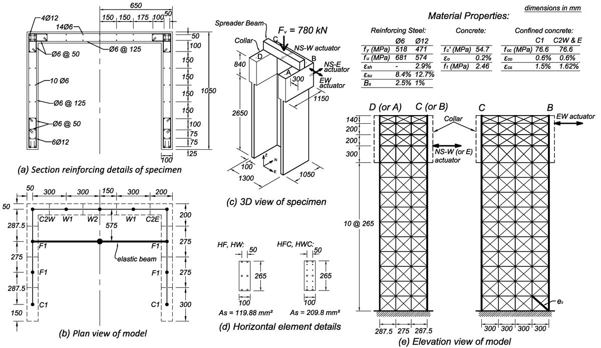
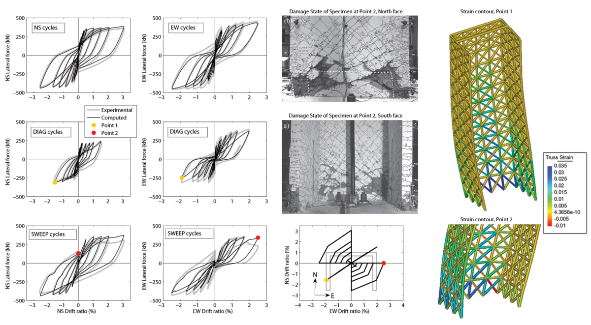
This example describes the Opensees implementation of a nonlinear beam-truss model for a RC wall with a C-shaped section subject to multi-axial loading. The response of Wall TUB from Beyer et al. (2008) is studied in this example and the experimental and computed response will be compared in the results.
See the video of the simulation here!
Model Description
Specimen TUB was a C-shape section wall with shear span (M/VL) = 2.8 in the E-W direction and 2.6 in the N-S direction, as shown in the figure below. The total applied axial load was 780 kN at the centroid of the section. One actuator was used in the E-W direction and two in the N-S direction to apply the lateral load, and a collar was used at the top of the wall for the loading.
For the corresponding beam-truss model, shown below, the vertical and horizontal elements represent the respective reinforcing bars and their surrounding concrete in the respective direction. The diagonal elements (Truss2 Elements with ConcretewBeta material) span between each node in the model. Details for the beam-truss model, material model parameters, and analysis are presented in Lu and Panagiotou (2013).
Results
The cyclic computed response in all directions considered was in very good agreement with the experimentally measured for all cycles. In very good agreement with the experimentally observed diagonal crushing, the model computed crushing of the concrete the base at element e2, see the above figure, in the segment of the wall parallel to the EW direction during the sweep cycle of 3% peak drift ratio.
A video of the simulation, including displacement shapes and strain contours for all cycles, can be found here.
References
[1] Beyer, K., Dazio, A., and Priestley, M. J. N.(2008). "Quasi-Static Cyclic Tests of Two U-Shaped Reinforced Concrete Walls." Journal of Earthquake Engineering, 12:7, 1023-1053.
[2] Lu, Y., and Panagiotou, M. (2013). “Three-Dimensional Nonlinear Cyclic Beam-Truss Model for Reinforced Concrete Non-Planar Walls.” Journal of Structural Engineering, published online.

