Truss Model Example - Squat RC Wall
Example prepared by: Yuan Lu, UC Berkeley and Marios Panagiotou, UC Berkeley
This example describes the Opensees implementation of a nonlinear truss model for a squat shear critical wall subject to static cyclic loading. The response of Wall WP1105-8 from Massone Sanchez (2005) is studied in this example and the experimental and computed response will be compared in the results.
For this example, the following files are available (download together in MassoneWall_TrussExample.zip):
- MassoneWall_TrussModel.tcl - main file for creating and analyzing the model
- MassoneWall_inputCyclic.dat - cyclic displacement history file
- MassoneWall_plotResults.m - useful matlab file for generating the plots shown
Model Description

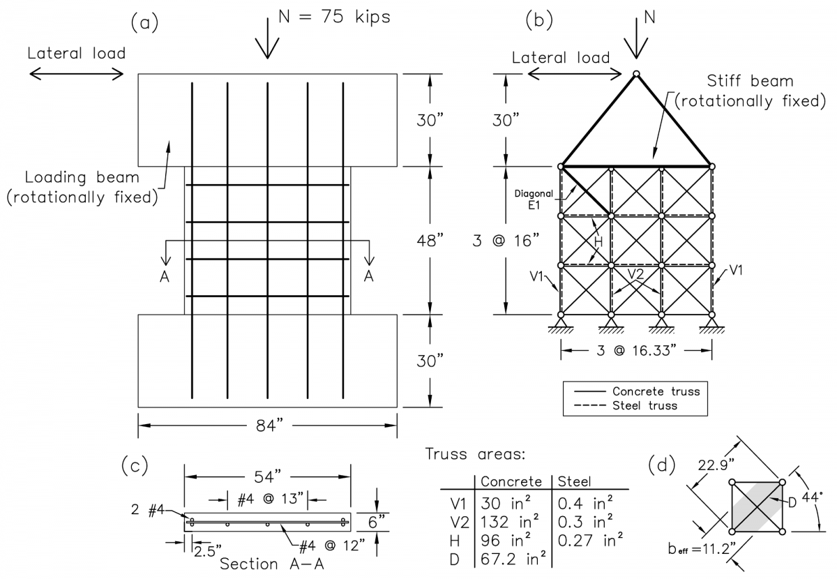
Figure 1(a) shows the dimension and reinforcing details of Wall WP1105-8, see Massone Sanchez (2005). The wall had an almost square aspect ratio (54” wide and 48” tall) with longitudinal and transverse reinforcement ratios ρw = 0.43% and ρt = 0.27%, respectively. The compressive axial load N = 75 kips and remained constant during the test. The lateral force was applied to the top of the wall through the top loading beam; the loading beam was constrained from rotation.
For the corresponding truss model, shown in Figure 1(c), the vertical and horizontal trusses (Truss Elements) represent the respective reinforcing bars and their surrounding concrete in the respective direction. The location of the outer vertical truss coincides with the position of the outer longitudinal reinforcements with the location of the inner trusses distributed to allow for equidistant spacing. The areas of concrete and steel used in these elements are listed in Figure 1. The diagonal elements (Truss2 Elements) span between each node in the model and have an effective width [beff as shown in Figure 1(d)] equal to 11.2”.
The general application of the truss modeling approach can be found in Panagiotou et al (2012), including the truss model for this wall implemented in Ruaumoko and more examples of truss models for both squat and slender walls. Lu and Panagiotou (2013) presents a 3D nonlinear cyclic beam-truss model for non-planar walls that also uses the Truss2 element used here.
Material Models
Figure 2 shows the uniaxial cyclic behavior of the vertical and diagonal concrete material models (ConcretewBeta material) and the steel material model (ReinforcingSteel material). The biaxial effect of normal tension is considered for the diagonal elements only, and the input parameters for the diagonal concrete material are listed below. More details on the implementation and behavior of these materials can be found in their respective pages.

| $fpc | -4.63 ksi |
| $ec0 | -0.002 |
| $fcint, $ecint | -0.001 ksi, -0.0041 |
| $fcres, $ecres | 0. ksi, -1. |
| $ftint | 0.001 ksi |
| $ftint, $etint | 0. ksi, 1.0 |
| $ftres, $etres | 0. ksi, 1.0 |
| $Ec | 4000. ksi |
| $alpha | 0.5 |
| $lambda | 0.75 |
| $bint $ebint | 0.3, 0.0103 |
| $bres $ebres | 0.1, 0.0258 |
For the concrete used in the vertical, horizontal, and diagonal directions, mesh objectivity is used to define the softening in compression and tension as well as for the normal strains associated with specific values of beta. The method of fracture energy for determining the softening slope is explained in Lu and Panagiotou (2013) and the same values, with a reference length of 600 mm = 23.6”, is used.
Analysis
The wall is loaded with the gravity load of 75 kips before the cyclic analysis. This is analyzed separately using 10 steps of load control. Following that, the gravity loads are kept constant while the lateral displacements are applied at the top node of the truss model, as show in Figure 1. The lateral displacement is done by displacement control with a displacement increment of 1e-4 inches per step, which is equivalent to 540 steps for each 0.1% drift.
Results

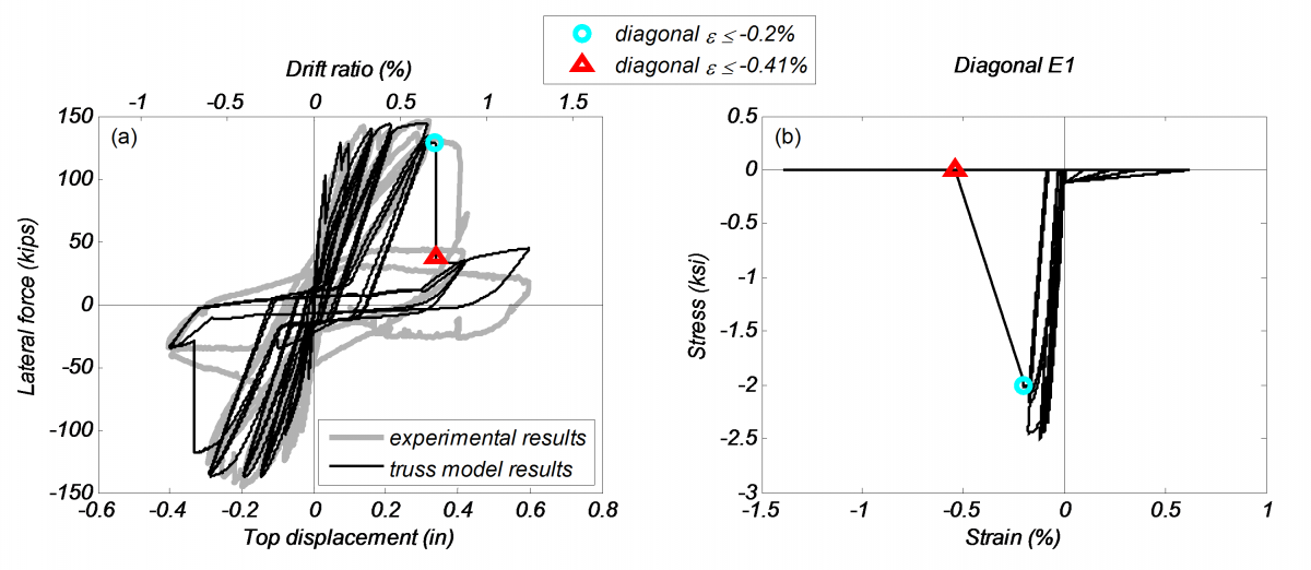
Figure 3(a) shows the comparison of experimentally measured and numerically computed global lateral force-displacement response. The figure marks the points where the diagonal strain first exceeds 0.2% and 0.41% compression strain, corresponding to the instance of peak uniaxial compression strength and 0 compression strength, respectively.
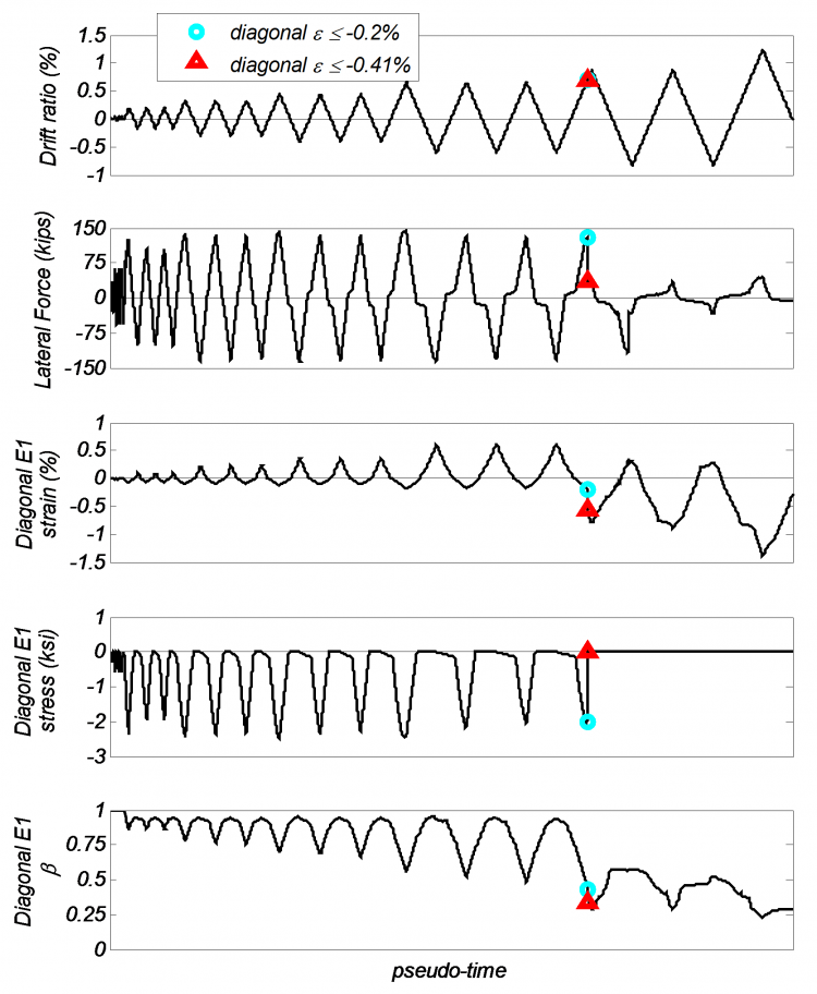
The experiment resulted in diagonal crushing of the concrete at a drift ratio of 0.85%; the analytical model computed the crushing of the diagonal concrete at 0.7% drift in Diagonal E1 [shown in Figure 1(b)]. Figure 3(b) shows the stress-strain history of Diagonal E1, showing the compression strength reduction due to normal tension strain. Figure 2 shows the pseudo-time history of drift ratio, lateral force, and strain, stress, and beta for Diagonal E1.

References
[1] Massone Sanchez, L. M. (2006). “RC Wall Shear—Flexure Interaction: Analytical and Experimental Responses.” PhD thesis, University of California, Los Angeles, Los Angeles, CA, 398 pp.
[2] Panagiotou, M., Restrepo, J.I., Schoettler, M., and Kim G. (2012). "Nonlinear cyclic truss model for reinforced concrete walls." ACI Structural Journal, 109(2), 205-214.
[3] Lu, Y., and Panagiotou, M. (2013). “Three-Dimensional Nonlinear Cyclic Beam-Truss Model for Reinforced Concrete Non-Planar Walls.” Journal of Structural Engineering, published online.