ConcretewBeta Material
This command is used to construct a uniaxial concrete material object which accounts for the biaxial strain field on the concrete compressive behavior as in Vecchio and Collins (1986). Compressive stress-strain envelope is based on the Fujii concrete model (Hoshikuma et al. 1997), options for tri-linear softening behavior in tension and compression as well as tension stiffening based on Stevens et al. (1991) is available.
This model uses a tri-linear relation between normal tensile strain and compressive stress. This material model must be used with the Truss2 or CorotTruss2 elements in order to account for normal strains.
| uniaxialMaterial ConcretewBeta $matTag $fpc $ec0 $fcint $ecint $fcres $ecres $ft $ftint $etint $ftres $etres <-lambda $lambda> <-alpha $alpha> <-beta $bint $ebint $bres $ebres> <-M $M> <-E $Ec> <-conf $fcc $ecc> |
| $matTag | integer tag identifying material |
| $fpc | peak unconfined concrete compressive strength* |
| $ec0 | compressive strain corresponding to unconfined concrete compressive strength* |
| $fcint, $ecint | intermediate stress-strain point for compression post-peak envelope* |
| $fcres, $ecres | residual stress-strain point for compression post-peak envelope* |
| $ftint | tensile strength of concrete |
| $ftint, $etint | intermediate stress-strain point for tension softening envelope |
| $ftres, $etres | intermediate stress-strain point for tension softening envelope |
| Optional: | |
| $lambda | controls the path for unloading from compression strain (default 0.5) |
| $alpha | controls the path for unloading from tensile strain (default 1) |
| $bint $ebint | intermediate β-strain point for for biaxial effect (default 1 0) |
| $bres $ebres | residual β-strain point for for biaxial effect (default 1 0) |
| $M | factor for Stevens et al. (1991) tension stiffening (default 0; see Note 2) |
| $Ec | initial stiffness (default 2 * $fpc / $ec0; see Note 3) |
| $fcc $ecc | confined concrete peak compressive stress and corresponding strain* (see Eq. 1) |
NOTES:
(1) *Compressive concrete parameters should be input as negative values.
(2) For non-zero $M, the tension stiffening behavior will govern the post-peak tension envelope. Tri-linear tension softening parameters $ftint, $etint, $ftres, $etres will have no effect, but dummy values must be inputted.
(3) Value of $Ec must be between $fpc / $ec0 and 2 * $fpc / $ec0 otherwise the closest value will be assigned.
IMPLEMENTATION:
- Uniaxial Behavior
Figure 1. ConcretewBeta material model behavior based on specified input parameters

The above figure shows the shape of the compression and tension envelopes, based on the specified input parameters. If the confined concrete option is given, the compression loading envelope is defined as:
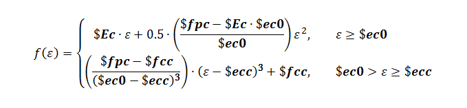
Equation 1.

up until strain $ecc. If the confined concrete option is not specified, the above equation for compression strains less than $ec0 is used. Following this region, the compression envelope goes linear to the points ($ecint, $fcint) and ($ecres, $fcres) in that order. For compression strains larger than $ecres, a residual stress value of $fcres is used.
Unloading from compression strain, the following slope is used:
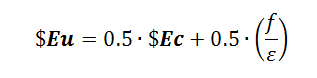
Equation 2.

until reaching zero stress, which then reloads linearly to the point with the largest tensile strain that occurred before.
The tension envelope is linear until it reaches the specified tension strength $ft. If the tension stiffening parameter $M is not specified, the tension envelope after reaching $ft will go linearly to the specified points of ($etint, $ftint) and ($etres, $ftres) in that order. For tensile strains larger than $etres, a residual stress value of $fcres is used. If the tension stiffening parameter is specified, the concrete softens as per Stevens et al. (1991):
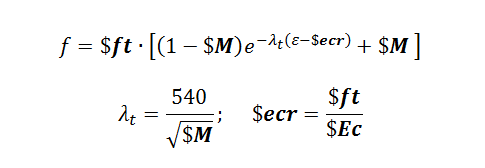
Equation 2.

Unloading from tension strain, a slope of $Ec, the initial material tangent, is used. After reaching zero stress, the material targets a compression stress equal to -$alpha*$ft at zero strain. Thereafter, the material loads linearly to the point where the peak compressive strain occurred. In the case where the slope leading to this target point is less than that for the point with stress -$alpha*$ft at zero strain, the material reloads directly to the point where peak compressive strain occurred without passing through the point with stress -$alpha*$ft at zero strain.
- Biaxial Behavior
Figure 2. Relation between concrete compressive stress reduction factor, β, and normal tensile strain, εn

The ConcretewBeta material model accounts for the biaxial strain field on the concrete compressive behavior when used in conjunction with the Truss2 element, which gives the instantaneous normal tensile strain. Figure 2 above shows the relationship between the β factor and the normal tensile strain, based on the specified input parameters. For compressive stresses, the instantaneous stress value computed by the material is given to be β*fc where fc is the compressive stress given by the uniaxial behavior described above and β is determined from the instantaneous normal strain given by the Truss2 element. The β factor has no effect on the tension stress.
At zero normal tensile strain, β = 1, resulting in no reduction of compression strength. With increasing normal tensile strain, the β factor goes linearly to the specified points of ($ebint, $bint) and ($ebres, $bres) in that order. For normal tensile strains larger than $ebres, a residual β value of $bres is used.
EXAMPLES:
to be added
REFERENCES:
Lu, Y., and Panagiotou, M. (2013). “Three-Dimensional Nonlinear Cyclic Beam-Truss Model for Reinforced Concrete Non-Planar Walls.” Journal of Structural Engineering, published online.
Bazant, Z. P. and Planas, J. (1998). “Fracture and size effect in concrete and other quasibrittle materials.” Boca Raton, FL: CRC Press.
Hoshikuma, J., Kawashima, K., Nagaya, K., and Taylor, A. W. (1997). “Stress-strain model for confined reinforced concrete in bridge piers.” Journal of Structural Engineering, 123(5), 624-633.
Stevens, N. J., Uzumeri, S. M., Collins, M. P., and Will, T. G. (1991). “Constitutive model for reinforced concrete finite element analysis.” ACI Structural Journal, 88(1), 49-59.
Vecchio, F. J., and Collins, M. P. (1986). “The modified compression field theory for reinforced concrete elements subjected to shear.” Journal of the American Concrete Institute, 83(2), 219-231.
Code Developed by: Yuan Lu, UC Berkeley and Marios Panagiotou, UC Berkeley