Response Sensitivity Analysis
User Manual Provided by: Quan Gu (UCSD), Joel P. Conte (UCSD), Michele Barbato (LSU),Yong Li (UCSD)
This article describes the basic OpenSees features needed for the simulation of vertically propagating shear waves in a scale model in a centrifuge. GID has been used for pre- and post- processing. For relatively simple configurations (even the one used in this paradigm) a pre-processor might not be needed, but a post-processor is necessary to visualize field output results. For every presented feature an example command is excerpted from the example tcl file and explained in detail. This tutorial does not explain though in every detail all the options associated in the various commands used. For this, the reader is directed to the OpenSees manual (the most recent is the on-line version of it). The commands and features used in this analysis have been tested with OpenSees versions 1.74, 1.75 and 2.0 but should also work for newer versions too. In case an example does not work, I would be obliged to hear about possible problems at avytin [at] mit . edu.
This manual explains how one can create a .tcl file that could be read and executed by the OpenSees interpreter. Notice should be taken that OpenSees is dimensionless, so the user must make sure that he uses a consistent system of units (e.g. SI).
Once an example.tcl file has been created, the user can then simply run OpenSees.exe, and in turn, write in the command line of the interpreter "source example.tcl" to run his analysis.
Simulated Geometry
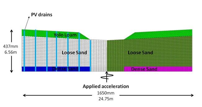
The centrifuge model geometry that we need to simulate is shown below. The model consists of two blocks of dense sand. On top of this lies a layer of loose liquefiable sand and on the top there are two facing slopes of Yolo Loam. The right hand side is treated with earthquake drains (PV-Drains) to accelerate the dissipation of excess pore pressure. An acceleration pattern is applied on the bottom of the model.
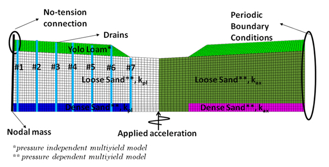
In the figure below, the most important finite element modelling features used in OpenSees are presented. These are explained in more detail in the next sections.
Elements Used
The elements used in this simulation are described in this section.
The Yolo Loam layer is simulated using total stress analysis with 4-noded quad elements. This element can be used to perform drained analysis, total stress analysis, and undrained analysis when coupled with the FluidSolidPorousMaterial material wrapper. An example of this command taken from the example's code is:
element quad 1 2327 2351 2326 2302 1.0 "PlaneStrain" 1 $press 1.3 $gravX $gravY'''
This command defines a planestrain quad element with id 1, that connects the nodes 2327, 2351, 2326, and 2302. The element has an out-of-plane width of 1 unit. The mechanical behavior is prescribed by material 1. The hydrostatic pressure of the element is the value of press. The total density of the material in the quad element is 1.3. The gravitational components in both directions are defined by the values of the parameters gravX and gravY.
The sand layer is simulated using 4-noded quadUP elements. These elements have three degrees of freedom per node: two for displacements, and one for pore pressure. It is important to keep in mind that the velocity, and not the displacement, of the 3rd DOF is the pore pressure, when requesting output or applying pore pressure conditions on the model. These elements can be used to model coupled pore pressure displacement analysis following the u-p formulation. Since they are four-noded they are expected not to perform very well in situations where they simulate incompressible behavior (e.g. undrained conditions). For completely undrained conditions the previously mentioned quad elements should be used together with the FluidSolidPorousMaterial material wrapper. An example how to define a quadUP element is:
element quadUP 417 4190 4191 4200 4199 1.0 3 $bulk 1. [expr 0.0003/9.81/1.] [expr 0.0003/9.81/1.] $gravX $gravY $press
This command creates a 4-noded planestrain quadUP element with id 417 that connects the nodes 4190, 4191, 4200, 4199. The element has a out-of-plane width of 1 unit. The mechanical behavior is prescribed by material 3. The bulk modulus of the pore fluid is the value of the variable bulk. The fluid mass density is 1. The hydraulic conductivity is k=0.0003. The gravitational components are defined by the values of the parameters gravX and gravy. The element also has a hydrostatic compression equal to the value of the variable press.
The soil material on the Yolo loam layer, where the effective stresses are small, should be able to disconnect from the laminar box. In order for this behavior to be modeled correctly, a zeroLength element should be defined. A zeroLength element connects two nodes that have the same, or almost the same coordinates according to an internally pre-specified threshold. The mechanical properties of this connection are defined by a uniaxial material which is attached to the zeroLength element. A sample definition of this type of element is:
element zeroLength 3933 4205 4221 -mat 7 7 -dir 1 2
This command creates a zeroLength element with id 3933 that connects the nodes 4205 and 4221. The mechanical behavior of this connection is prescribed by the uniaxial material 7 in direction 1 and by the same material in direction 2.

