One-dimensional Consolidation: Difference between revisions
(Created page with 'Example posted by: <span style="color:blue"> Christopher McGann, University of Washington</span> ---- This article describes the OpenSees implementation of a 1D consolidation m...') |
No edit summary |
||
| Line 9: | Line 9: | ||
Download them all in a compressed file: [[Media:consolidation.zip|consolidation.zip]] | Download them all in a compressed file: [[Media:consolidation.zip|consolidation.zip]] | ||
To run this example, the user must download the file [[1Dconsolidation.tcl|1Dconsolidation.tcl]]. Once this has been done, the user can then type "source | To run this example, the user must download the file [[1Dconsolidation.tcl|1Dconsolidation.tcl]]. Once this has been done, the user can then type "source 1Dconsolidation.tcl" into the interpreter of the OpenSees.exe application to run the analysis. The Matlab scripts are not essential to the analysis, however, they are provided to demonstrate how certain plots can be obtained from the recorded output. | ||
== Model Description == | == Model Description == | ||
[[File:consolModel.png|frame|Fig 1. Schematic representation of the consolidation model. Blue nodes are corner nodes. Red nodes are interior nodes.]] | [[File:consolModel.png|frame|Fig 1. Schematic representation of the consolidation model. Blue nodes are corner nodes. Red nodes are interior nodes.]] | ||
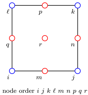
The one-dimensional consolidation model consists of a column of 9-node quadrilateral elements. These elements have two sets of nodes; the corner nodes have 3 degrees-of-freedom (2 displacement, 1 pore pressure), and the interior nodes have 2 displacement degrees-of-freedom only. These elements do not display the locking behavior associated with 4-node quadrilateral elements with pore pressure degrees-of-freedom, though the connectivity becomes more complex. A schematic depicting the 1D consolidation model is provided in Fig. 1. In this diagram, the corner nodes are blue and the interior nodes are red. | |||
This example is able to consider both single and double drainage conditions for the soil layer. The user can specify the desired drainage condition using the variable <tt>drainage</tt>. Setting <tt>drainage</tt> to 1 gives single drainage, with zero pore pressure at the top of the soil layer. Setting <tt>drainage</tt> to 2 gives double drainage, with zero pore pressure at the top and bottom of the soil layer. | |||
=== Mesh Geometry === | === Mesh Geometry === | ||
The geometry of the finite element mesh used for this example is dependent on several parameters which must be specified by the user. These include the number and size of the elements in the horizontal direction (default values are 1.0) and the number and size of the elements in the vertical direction. In this example, there are 10 elements in the vertical direction, and the elements are square. | |||
=== Corner Nodes === | === Corner Nodes === | ||
The corner nodes of the elements (depicted in blue in Fig. 1) are created in two dimensions, with three degrees-of-freedom (DOF). The first two DOF are displacements in the horizontal and vertical directions. The third DOF is for pore pressure. The input file provided with this example automatically generates the corner nodes in the proper locations depending on the parameters defined in the mesh geometry section. | |||
All of the corner nodes are fixed against horizontal translation (first DOF). The nodes on the lower boundary are fixed against both horizontal and vertical translations. | |||
The corner nodes at the upper boundary of the soil layer are fixed in the pore pressure DOF for the single and double drainage cases, while the corner nodes at the lower boundary are only fixed in the pore pressure DOF for the double drainage case. | |||
=== Interior Nodes === | === Interior Nodes === | ||
The interior nodes of the elements (depicted in red in Fig. 1) are created in two dimensions, with two DOF. The input file provided with this example automatically generates these nodes in the proper locations based on the specified parameters in the mesh geometry section. | |||
The single interior node at the lower boundary is fixed against horizontal and vertical translation. The interior nodes on the edges of the soil column are fixed against horizontal displacements. | |||
The nodes on the upper boundary of the soil layer (both corner and interior) are given equal displacement DOF using the [[equalDOF command]]. | |||
=== Soil Material === | === Soil Material === | ||
The soil in this example is assumed to be cohesive, therefore the nDMaterial [http://opensees.berkeley.edu/OpenSees/manuals/usermanual/1558.htm PressureIndependMultiYield] is used for the soil constitutive model. The various required material parameters are defined for this constitutive model based upon the assumed soil type. The cohesive soil is assumed to be homogenous within the soil layer, therefore only a single material object is defined. | |||
=== Soil Elements === | === Soil Elements === | ||
Revision as of 00:08, 17 August 2010
Example posted by: Christopher McGann, University of Washington
This article describes the OpenSees implementation of a 1D consolidation model. A single soil column is modeled in two-dimensions, but all compression is one-dimensional. The model can consider either single or double drainage of the soil layer.
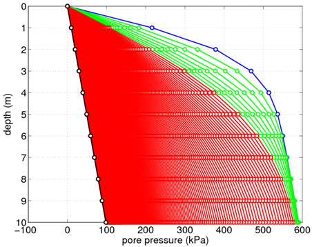
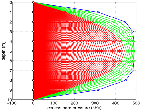
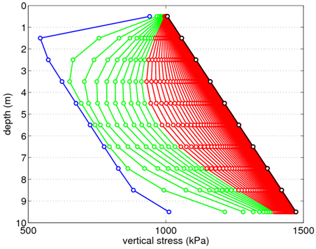
The input file needed to execute this analysis, 1Dconsolidation.tcl, is provided along with several helpful Matlab scripts to plot the results, plotPorePressure.m and plotStress.m.
Download them all in a compressed file: consolidation.zip
To run this example, the user must download the file 1Dconsolidation.tcl. Once this has been done, the user can then type "source 1Dconsolidation.tcl" into the interpreter of the OpenSees.exe application to run the analysis. The Matlab scripts are not essential to the analysis, however, they are provided to demonstrate how certain plots can be obtained from the recorded output.
Model Description
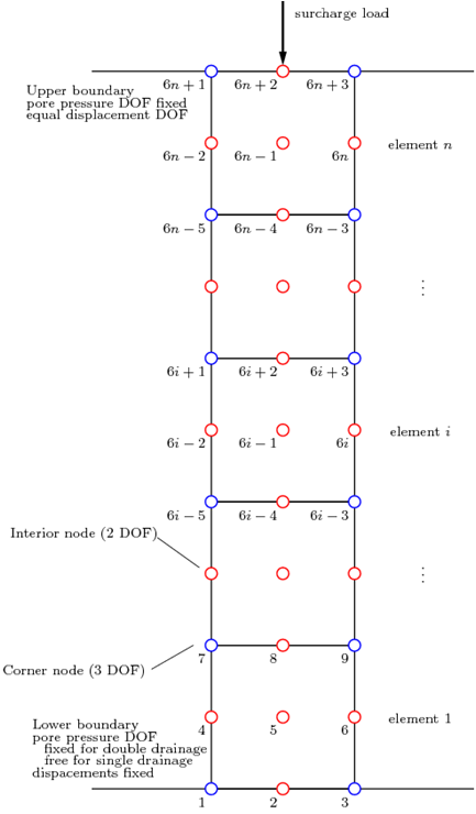
The one-dimensional consolidation model consists of a column of 9-node quadrilateral elements. These elements have two sets of nodes; the corner nodes have 3 degrees-of-freedom (2 displacement, 1 pore pressure), and the interior nodes have 2 displacement degrees-of-freedom only. These elements do not display the locking behavior associated with 4-node quadrilateral elements with pore pressure degrees-of-freedom, though the connectivity becomes more complex. A schematic depicting the 1D consolidation model is provided in Fig. 1. In this diagram, the corner nodes are blue and the interior nodes are red.
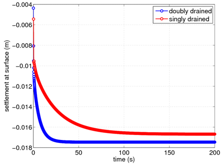
This example is able to consider both single and double drainage conditions for the soil layer. The user can specify the desired drainage condition using the variable drainage. Setting drainage to 1 gives single drainage, with zero pore pressure at the top of the soil layer. Setting drainage to 2 gives double drainage, with zero pore pressure at the top and bottom of the soil layer.
Mesh Geometry
The geometry of the finite element mesh used for this example is dependent on several parameters which must be specified by the user. These include the number and size of the elements in the horizontal direction (default values are 1.0) and the number and size of the elements in the vertical direction. In this example, there are 10 elements in the vertical direction, and the elements are square.
Corner Nodes
The corner nodes of the elements (depicted in blue in Fig. 1) are created in two dimensions, with three degrees-of-freedom (DOF). The first two DOF are displacements in the horizontal and vertical directions. The third DOF is for pore pressure. The input file provided with this example automatically generates the corner nodes in the proper locations depending on the parameters defined in the mesh geometry section.
All of the corner nodes are fixed against horizontal translation (first DOF). The nodes on the lower boundary are fixed against both horizontal and vertical translations.
The corner nodes at the upper boundary of the soil layer are fixed in the pore pressure DOF for the single and double drainage cases, while the corner nodes at the lower boundary are only fixed in the pore pressure DOF for the double drainage case.
Interior Nodes
The interior nodes of the elements (depicted in red in Fig. 1) are created in two dimensions, with two DOF. The input file provided with this example automatically generates these nodes in the proper locations based on the specified parameters in the mesh geometry section.
The single interior node at the lower boundary is fixed against horizontal and vertical translation. The interior nodes on the edges of the soil column are fixed against horizontal displacements.
The nodes on the upper boundary of the soil layer (both corner and interior) are given equal displacement DOF using the equalDOF command.
Soil Material
The soil in this example is assumed to be cohesive, therefore the nDMaterial PressureIndependMultiYield is used for the soil constitutive model. The various required material parameters are defined for this constitutive model based upon the assumed soil type. The cohesive soil is assumed to be homogenous within the soil layer, therefore only a single material object is defined.
Soil Elements
Gravity Loading
Recorders
Consolidation Analysis
Representative Results
