Eigen analysis of a two-story shear frame: Difference between revisions
No edit summary |
No edit summary |
||
| Line 41: | Line 41: | ||
</pre> | </pre> | ||
Masses are assigned at nodes 3, 4, 5, and 6 using [[Mass | Masses are assigned at nodes 3, 4, 5, and 6 using [[Mass Command|mass]] command. Since the considered shear frame system has only two degrees of freedom (displacements in x at the 1st and the 2nd storey), the masses have to be assigned in x direction only. | ||
<pre style="background:yellow;color:black;width:800px"> | <pre style="background:yellow;color:black;width:800px"> | ||
Revision as of 22:48, 30 July 2010
Example Provided by: Vesna Terzic, UC Berkeley
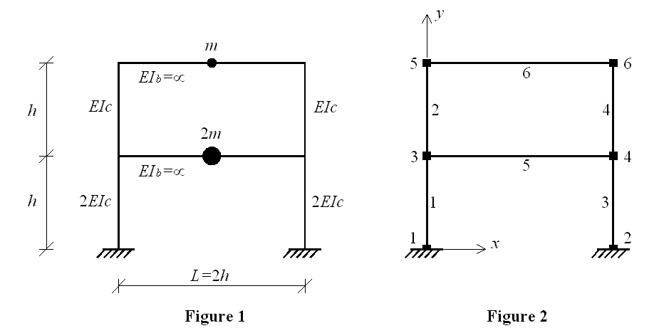
This example demonstrates how to perform eigenvalue analysis and plot mode shapes. Two-storey shear frame (Example 9.1a from "Dynamic of Structures" book by Professor Anil K. Chopra) is used for this purpose. Geometry and material characteristics of the frame structure are shown in Figure 1. Node and element numbering is given in Figure 2.
Instructions on how to run this example
To execute this ananlysis in OpenSees download this file: EigenAnal_twoStoreyShearFrame.tcl
To run this example, place the OpenSees.exe to the same directory with the downloaded file. By double cliking on OpenSees.exe the OpenSees interpreter will pop out. To run the analysis the user sholud type "source EigenAnal_twoStoreyShearFrame2-1.tcl" in OpenSees interpreter and hit enter. To create output files of eigenvectors (stored in directory "modes") the user has to exit OpenSees interpreter by typing "exit".
Create the model
Spatial dimension of the model and number of degrees-of-freedom (DOF) at nodes are defined using model command. In this example we have 2D model with 3 DOFs at each node. This is defined in the following way:
model BasicBuilder -ndm 2 -ndf 3
Nodes of the structure (Figure 2) are defined using the node command:
node 1   0.  0. ;
node 2   $L  0. ;
node 3   0.  $h ;
node 4   $L  $h ;
node 5   0.  [expr 2*$h];
node 6   $L  [expr 2*$h];
The boundary conditions are defined next using single-point constraint command fix. In this example nodes 1 and 2 are fully fixed at all three DOFs:
fix 1 1 1 1;
fix 2 1 1 1;
Masses are assigned at nodes 3, 4, 5, and 6 using mass command. Since the considered shear frame system has only two degrees of freedom (displacements in x at the 1st and the 2nd storey), the masses have to be assigned in x direction only.
mass 3 $Mass 0. 0. ;
mass 4 $Mass 0. 0. ;
mass 5 [expr $Mass/2.] 0. 0. ;
mass 6 [expr $Mass/2.] 0. 0. ;
In order to simulate shear frame action in the model
In this example, the beams and columns of the frame are defined elastic.