Infill Wall Model With In-Plane, Out-of-Plane Interaction and Element Removal During Simulation: Difference between revisions
Selimgunay (talk | contribs) No edit summary |
Selimgunay (talk | contribs) No edit summary |
||
| Line 22: | Line 22: | ||
[[Image:Figure2-1.jpg]] | [[Image:Figure2-1.jpg]] | ||
The parameters defining a fiber section (<math>\mathrm{A_i}\,</math>, <math>\mathrm{z_i}\,</math>, <math>\mathrm{f_{yi}}\,</math>, and <math>\mathrm{{\epsilon}_{yi}}\,</math>) are set such that the intended strength interaction (Figure 2b) and the IP axial and OOP bending stiffness values of the diagonal infill wall element are properly simulated. In the current formulation, FEMA-356[3] or ASCE-41[4] equations are used for calculating the axial stiffness and unidirectional strength in the IP direction. However, any other relationships that the user considers as suitable can also be employed. The OOP mass, stiffness and unidirectional bending strength are calculated such that the model has the same natural frequency as the original infill wall, it should produce the same support reactions where it is attached to the surrounding frame for a given support motion (story acceleration), and it should exhibit initial yielding at the same level of support motion that causes the original infill wall to yield. Discretization of the inelastic fiber section is explained below. In the explanation, equations of FEMA-356 are referred to rather than ASCE-41 equations, since FEMA-356 document is accessible from FEMA website. However, Equations of FEMA-356 and ASCE-41 are very similar and ASCE-41 equations may be replaced with FEMA-356 equations. | |||
Revision as of 05:23, 18 April 2010
This article is still under development.
M. Selim Gunay and Khalid M. Mosalam, University of California, Berkeley
This article describes the commands for modeling an infill wall element which considers in-plane and out-of-plane interaction and for removal of the element during nonlinear time history simulation in OpenSees. In addition, the infill wall model and element removal algorithm are briefly described. Interested readers can refer to the mentioned references for more information. Questions or comments can be directed to selimgunay [at] berkeley . edu or mosalam [at] ce . berkeley . edu
Modeling of the Infill Wall
The described infill wall model is a model which considers the interaction of in-plane (IP) and out-of-plane (OOP) effects. Modeling of the infill wall is performed by using the available OpenSees materials, sections, elements and tcl commands. The infill wall model is comprised of two equal size diagonal beamWithhinges elements and a midspan node with OOP mass (Figure 1). The inelastic fiber section assigned to the ends of the elements connected to the midspan node is discretized as explained in the following paragraph. Elastic sections with very small moment of inertia (to simulate moment release) are assigned to the ends attached to the surrounding frame. The hinge length near the midspan node is selected as short as possible in order to produce a relatively sharp yield point for the element, while at the same time providing a numerically stable solution. 1/10 of the total length of the diagonal is a suitable value for the total hinge length (sum of the lengths of the hinges on both sides of the node). The hinge length on the other end can be selected as small as possible without losing numerical stability.
Discretization of Inelastic Fiber Section and Calculation of OOP mass
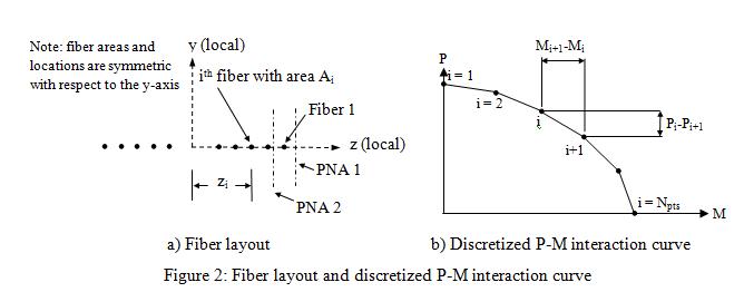
The inelastic fiber section of the beamWithhinges element is modeled by strategically locating a collection of nonlinear fiber elements[1,2]. The fibers are located along a line in the OOP direction (Z-direction in Figure 1). By this way, the beam-column element acts as a truss element and a flexural element in the IP and OOP directions, respectively. The discretization of the cross section is shown in Figure 2a. In this figure, the vector used to define the local-coordinate system in OpenSees, “vecxz”, is (0 0 -1) corresponding to the global axes shown in Figure 1. Each fiber is defined with the area <math>\mathrm{A_i}\,</math>, z-coordinate <math>\mathrm{z_i}\,</math> and a bilinear stress-strain relationship. The strain hardening slope is chosen to be very small, hence the yield stress <math>\mathrm{f_{yi}}\,</math> and the yield strain <math>\mathrm{{\epsilon}_{yi}}\,</math> define the stress-strain relationship of the <math>\mathrm{i_{th}}\,</math> fiber. Since only one diagonal is utilized in the model, it has both tension and compression strengths. Therefore, the fibers are considered to have the same absolute value for the tensile and compression yield strengths.
The parameters defining a fiber section (<math>\mathrm{A_i}\,</math>, <math>\mathrm{z_i}\,</math>, <math>\mathrm{f_{yi}}\,</math>, and <math>\mathrm{{\epsilon}_{yi}}\,</math>) are set such that the intended strength interaction (Figure 2b) and the IP axial and OOP bending stiffness values of the diagonal infill wall element are properly simulated. In the current formulation, FEMA-356[3] or ASCE-41[4] equations are used for calculating the axial stiffness and unidirectional strength in the IP direction. However, any other relationships that the user considers as suitable can also be employed. The OOP mass, stiffness and unidirectional bending strength are calculated such that the model has the same natural frequency as the original infill wall, it should produce the same support reactions where it is attached to the surrounding frame for a given support motion (story acceleration), and it should exhibit initial yielding at the same level of support motion that causes the original infill wall to yield. Discretization of the inelastic fiber section is explained below. In the explanation, equations of FEMA-356 are referred to rather than ASCE-41 equations, since FEMA-356 document is accessible from FEMA website. However, Equations of FEMA-356 and ASCE-41 are very similar and ASCE-41 equations may be replaced with FEMA-356 equations.

