Getting Started with OpenSees -- Problem Definition: Difference between revisions
Jump to navigation
Jump to search
No edit summary |
No edit summary |
||
| Line 2: | Line 2: | ||
The structural model consists of the planar portal frame shown in the figure below: | The structural model consists of the planar portal frame shown in the figure below: | ||
[[File: | |||
[[File:GettingStartedGeometry.JPG|link=Getting Started with OpenSees -- Problem Definition]] | |||
Revision as of 06:25, 28 November 2009
A portal frame will be used to demonstrate the OpenSees commands. A structural model will be defined first. Subsequently, a number of static and dynamic analyses will be defined and implemented.
The structural model consists of the planar portal frame shown in the figure below:
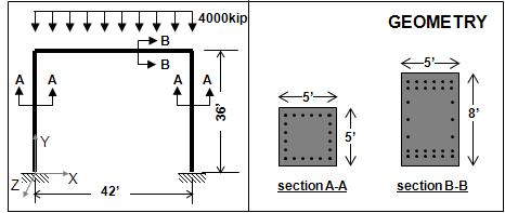
The columns and beam will be modeled as elastic elements. At a more advanced level, these elements can be replaced by more refined element models.
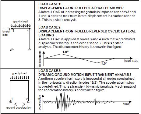
In the analysis phase, the frame will be subjected to three different load cases:
- DISPLACEMENT-CONTROLLED LATERAL PUSHOVER;
- DISPLACEMENT-CONTROLLED REVERSED CYCLIC LATERAL LOADING;
- DYNAMIC GROUND-MOTION-INPUT TRANSIENT ANALYSIS.
In all cases, however, the frame will be subjected to constant static gravity loads:
Return to Getting Started with OpenSees