ConcretewBeta Material: Difference between revisions
mNo edit summary |
mNo edit summary |
||
| (9 intermediate revisions by the same user not shown) | |||
| Line 5: | Line 5: | ||
See the '''[[#Examples|Examples Section]]''' for the use of this material model in truss models for planar RC walls and a beam-truss model for a non-planar wall loaded biaxially. | See the '''[[#Examples|Examples Section]]''' for the use of this material model in truss models for planar RC walls and a beam-truss model for a non-planar wall loaded biaxially. | ||
::[[File:BeyerTUB point770.jpg|thumb|upright=2.0|alt=RC | ::[[File:BeyerTUB point770.jpg|thumb|upright=2.0|alt=RC C-shaped wall |Reinforced concrete wall with a C-shaped section subject to multi-axial loading, described in [[#Examples|the examples]].]] | ||
{| | {| | ||
| Line 85: | Line 85: | ||
  Figure 2 shows the relationship between concrete compressive stress reduction factor, ''β'', and the normal tensile strain, ε<sub>n</sub>. For compressive stresses, the instantaneous stress value computed by the material is ''β''*''f<sub>c</sub>'' where ''f<sub>c</sub>'' is the compressive stress given by the uniaxial behavior described above. For positive (tensile) stress, ''β'' = 1. For compressive stress, the ''β''-ε<sub>n</sub> relationship is tri-linear and passes through the points (0,1), ('''$ebint''', '''$bint'''), and ('''$ebres''', '''$bres''') in that order. For normal tensile strains larger than '''$ebres''', ''β'' = '''$bres'''. |   Figure 2 shows the relationship between concrete compressive stress reduction factor, ''β'', and the normal tensile strain, ε<sub>n</sub>. For compressive stresses, the instantaneous stress value computed by the material is ''β''*''f<sub>c</sub>'' where ''f<sub>c</sub>'' is the compressive stress given by the uniaxial behavior described above. For positive (tensile) stress, ''β'' = 1. For compressive stress, the ''β''-ε<sub>n</sub> relationship is tri-linear and passes through the points (0,1), ('''$ebint''', '''$bint'''), and ('''$ebres''', '''$bres''') in that order. For normal tensile strains larger than '''$ebres''', ''β'' = '''$bres'''. | ||
==Examples== | ==Examples== | ||
===20-story RC core wall buildings: conventional fixed-base ('''[http://youtu.be/r14GDOB9tgY video]'''), rocking wall ('''[http://youtu.be/DmEwyWwcRP4 video]'''), and base isolation with rocking wall ('''[http://youtu.be/FBj-mNos8gU video]''') === | |||
[[Image:20story_samplePic2.png|1200px |alt=20-story core walls]] | |||
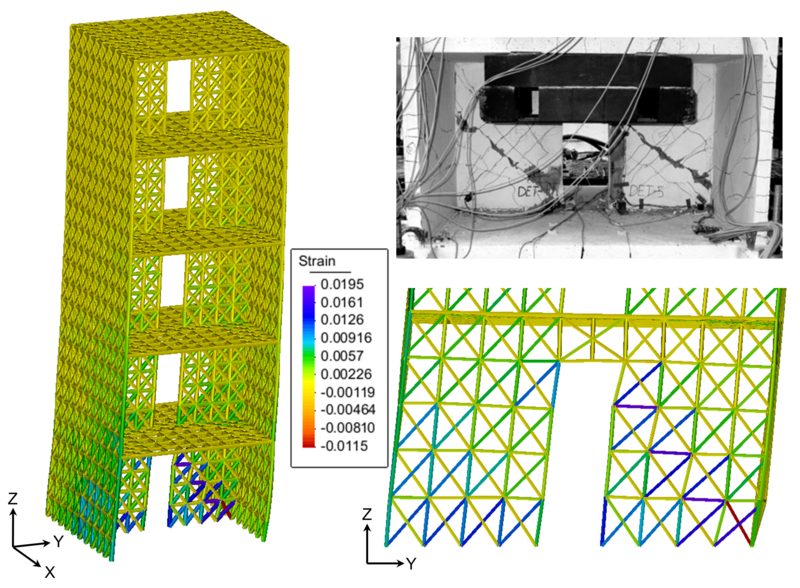
===5-story coupled wall specimen with diagonal tension failure, see: '''[http://youtu.be/a26aZiU5RgY Video of the simulation]'''=== | |||
[[Image:5story_samplePic.png|800px|link=http://youtu.be/a26aZiU5RgY |alt=RC coupled wall]] | |||
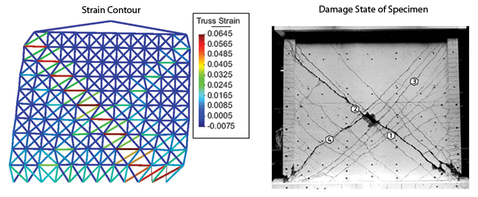
===See: '''[[Truss Model Example - Mestyanek Squat Wall| Truss Model - Mestyanek (1986) Squat RC Wall]]''' and '''[http://youtu.be/lQpzwHF_Z94 Video of the simulation]'''=== | |||
[[Image:Mestyanek resultsPlot2.png|800px|link=Truss Model - Mestyanek Squat Wall |alt=RC squat wall, Unit 1.0 tested by Mestyanek (1986)]] | |||
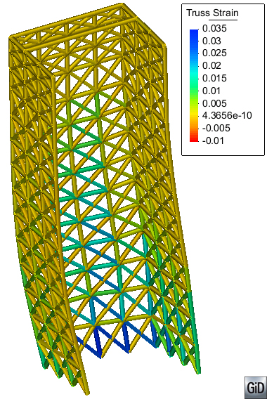
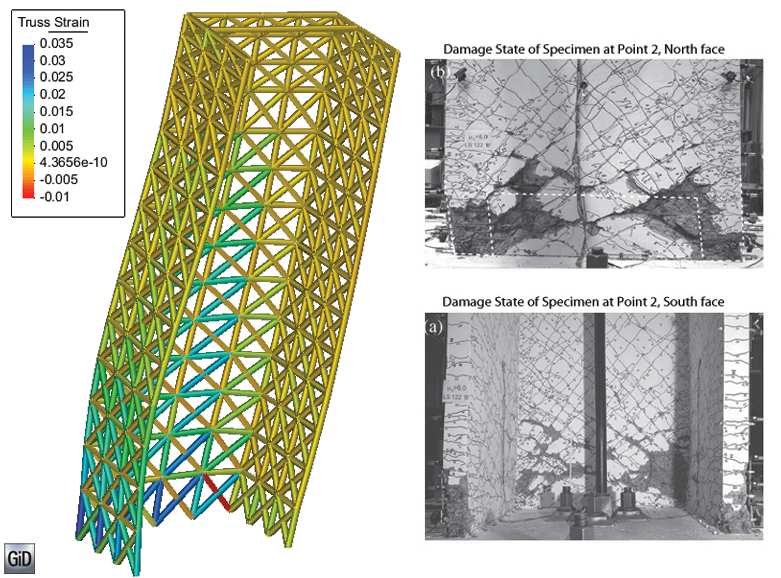
===See: '''[[Beam-truss Model Example - C-shaped RC Wall| Beam-truss Model - Beyer et al. (2008) RC Wall]]''' and '''[http://youtu.be/9O9Mev62Ilw Video of the simulation]'''=== | |||
[[File:BeyerWall fig2.png|800px|link=Beam-truss Model Example - C-shaped RC Wall |alt=non-planar RC wall, TUB tested by Beyer et al.]] | |||
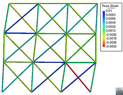
=== | ===See: '''[[Truss Model Example - Squat RC Wall| Truss Model - Massone Sanchez (2005) Squat RC Wall]]''' and '''[http://youtu.be/aq7r4HMAmvc Video of the simulation]'''=== | ||
[[File:MassoneWall displ1a.jpg|400px|link=Truss Model Example - Squat RC Wall |alt=RC squat wall, Wall WP1105-8 tested by Massone Sanchez(2005)]] | |||
==References== | ==References== | ||
Lu, Y., Panagiotou, M, and Koutromanos, I. (2014). "Three-dimensional beam-truss model for reinforced concrete walls and slabs subjected to cyclic static or dynamic loading." Report PEER 2014/18, Pacific Earthquake Engineering Research Center, University of California, Berkeley, Berkeley, CA. | |||
Lu, Y. and Panagiotou, M. (2014). “Earthquake Damage Resistant Multistory Buildings at Near Fault Regions using Base Isolation and Rocking Core Walls.” 1st Huixian International Forum on Earthquake Engineering for Young Researchers, August 16-19, Harbin, China. | |||
Lu, Y., and Panagiotou, M. (2014). “Three-Dimensional Nonlinear Cyclic Beam-Truss Model for Reinforced Concrete Non-Planar Walls.” Journal of Structural Engineering, 140 (3), DOI: 10.1061/(ASCE)ST.1943-541X.0000852. | |||
Panagiotou, M., Restrepo, J.I., Schoettler, M., and Kim G. (2012). "Nonlinear cyclic truss model for reinforced concrete walls." ACI Structural Journal, 109(2), 205-214. | |||
Beyer, K., Dazio, A., and Priestley, M. J. N.(2008). "Quasi-Static Cyclic Tests of Two U-Shaped Reinforced Concrete Walls." Journal of Earthquake Engineering, 12:7, 1023-1053. | |||
Hoshikuma, J., Kawashima, K., Nagaya, K., and Taylor, A. W. (1997). “Stress-strain model for confined reinforced concrete in bridge piers.” Journal of Structural Engineering, 123(5), 624-633. | Hoshikuma, J., Kawashima, K., Nagaya, K., and Taylor, A. W. (1997). “Stress-strain model for confined reinforced concrete in bridge piers.” Journal of Structural Engineering, 123(5), 624-633. | ||
Massone Sanchez, L. M. (2006). “RC Wall Shear—Flexure Interaction: Analytical and Experimental Responses.” PhD thesis, University of California, Los Angeles, Los Angeles, CA, 398 pp. | |||
Mestyanek, J. M. (1986). "The earthquake resistance of reinforced concrete structural walls of limited ductility." ME thesis. University of Canterbury. | |||
Stevens, N. J., Uzumeri, S. M., Collins, M. P., and Will, T. G. (1991). “Constitutive model for reinforced concrete finite element analysis.” ACI Structural Journal, 88(1), 49-59. | Stevens, N. J., Uzumeri, S. M., Collins, M. P., and Will, T. G. (1991). “Constitutive model for reinforced concrete finite element analysis.” ACI Structural Journal, 88(1), 49-59. | ||
---- | ---- | ||
Code Developed by: <span style="color:blue"> Yuan Lu, UC Berkeley </span> and <span style="color:blue"> Marios Panagiotou, UC Berkeley </span> | Code Developed by: <span style="color:blue"> Yuan Lu, UC Berkeley </span> and <span style="color:blue"> Marios Panagiotou, UC Berkeley </span> | ||
Latest revision as of 03:03, 4 February 2015
This command is used to construct a uniaxial concrete material object that explicitly considers for the effect of normal (to the axis where the material object is used) strain to the behavior of the concrete in compression. The compressive stress-strain envelope, up to the peak compressive strength(unconfined or confined) is based on the Fujii concrete model (Hoshikuma et al. 1997). The material has two options regarding the strength degradation in tension: (a) tri-linear or (b) nonlinear [based on the tension stiffening relation of Stevens et al (1991)]. The softening behavior in compression is tri-linear.
The model accounts for the effect of normal tensile strains on the concrete compressive behavior when used with the Truss2 or CorotTruss2 elements. See the Truss2 Element for description of how the normal strain is computed. The instantaneous stress is β*f where f is the computed stress and β is the compressive stress reduction factor which depends on the normal tensile strain, εn. The relation between εn and β (see the Biaxial Behavior Section) is tri-linear. Default values result in β = 1.
See the Examples Section for the use of this material model in truss models for planar RC walls and a beam-truss model for a non-planar wall loaded biaxially.
Reinforced concrete wall with a C-shaped section subject to multi-axial loading, described in the examples.

| uniaxialMaterial ConcretewBeta $matTag $fpc $ec0 $fcint $ecint $fcres $ecres $ft $ftint $etint $ftres $etres <-lambda $lambda> <-alpha $alpha> <-beta $bint $ebint $bres $ebres> <-M $M> <-E $Ec> <-conf $fcc $ecc> |
| $matTag | integer tag identifying material |
| $fpc | peak unconfined concrete compressive strength* |
| $ec0 | compressive strain corresponding to unconfined concrete compressive strength* |
| $fcint, $ecint | intermediate stress-strain point for compression post-peak envelope* |
| $fcres, $ecres | residual stress-strain point for compression post-peak envelope* |
| $ftint | tensile strength of concrete |
| $ftint, $etint | intermediate stress-strain point for tension softening envelope |
| $ftres, $etres | residual stress-strain point for tension softening envelope |
| Optional: | |
| $lambda | controls the path of unloading from compression strain (default 0.5) |
| $alpha | controls the path of unloading from tensile strain (default 1) |
| $bint $ebint | intermediate β-strain point for for biaxial effect (default 1 and 0, respectively) |
| $bres $ebres | residual β-strain point for for biaxial effect (default 1 and 0, respectively) |
| $M | factor for Stevens et al. (1991) tension stiffening (default 0; see Note 2) |
| $Ec | initial stiffness (default 2*$fpc/$ec0; see Note 3) |
| $fcc $ecc | confined concrete peak compressive stress and corresponding strain* (see Eq. 1) |
NOTES:
(1) *Parameters of concrete in compression should be specified as negative values.
(2) For non-zero $M, the tension stiffening behavior will govern the post-peak tension envelope. Tri-linear tension softening parameters $ftint, $etint, $ftres, $etres will have no effect, but dummy values must be specified.
(3) Value of $Ec must be between $fpc/$ec0 and 2*$fpc/$ec0 otherwise the closest value will be assigned.
Implementation
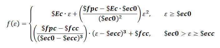
Equation 1. 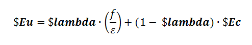
Equation 2. 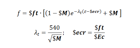
Equation 3.


Uniaxial Behavior
Figure 1 shows the compression and tension envelopes and the input parameters. The confined concrete envelope is defined by Equation 1 up to strain $ecc. The default values of $fcc and $$ecc are equal to $fpc and $ec0, respectively, for an an unconfined behavior. Following this region, the compression envelope is tri-linear and passes through the points ($ecint, $fcint) and ($ecres, $fcres) in that order. For compression strains larger than $ecres, the residual stress is $fcres.
For compression strain, the slope of the unloading branch is defined by Equation 2. After reaching zero stress, the material reloads linearly to the point with the largest tensile strain that occurred before.
The tension envelope is linear until it reaches $ft. If the tension stiffening parameter $M is not specified, the tension envelope after reaching $ft is tri-linear and passes through the points ($etint, $ftint) and ($etres, $ftres) in that order. For tensile strains larger than $etres, the residual stress is $fcres.
If $M is specified, the nonlinear tension stiffening behavior defined by Equation 3. It is suggested that $M = (75 mm)*ρl/db where ρl is the steel ratio in the direction parallel to the material direction and db is the bar diameter in mm.
The material unloads from tension strain using a slope of $Ec. After reaching zero stress, the material targets the point (0, -$alpha*$ft). Thereafter, the material loads linearly to the point where the peak compressive strain previously occurred. In the case where the slope leading to this target point is less than that for the point (0, -$alpha*$ft), the material reloads directly to the point where peak compressive strain occurred.
Figure 1. ConcretewBeta material model behavior based on specified input parameters

Figure 2. Relation between the concrete compressive stress reduction factor, β, and normal tensile strain, εn

Biaxial Behavior
The ConcretewBeta material model accounts for the biaxial strain field on the concrete compressive behavior when used in conjunction with the Truss2 element. The Truss2 element computes the strain normal to the direction of the element (see Truss2 Element).
Figure 2 shows the relationship between concrete compressive stress reduction factor, β, and the normal tensile strain, εn. For compressive stresses, the instantaneous stress value computed by the material is β*fc where fc is the compressive stress given by the uniaxial behavior described above. For positive (tensile) stress, β = 1. For compressive stress, the β-εn relationship is tri-linear and passes through the points (0,1), ($ebint, $bint), and ($ebres, $bres) in that order. For normal tensile strains larger than $ebres, β = $bres.
Examples
20-story RC core wall buildings: conventional fixed-base (video), rocking wall (video), and base isolation with rocking wall (video)

5-story coupled wall specimen with diagonal tension failure, see: Video of the simulation
See: Truss Model - Mestyanek (1986) Squat RC Wall and Video of the simulation
See: Beam-truss Model - Beyer et al. (2008) RC Wall and Video of the simulation
See: Truss Model - Massone Sanchez (2005) Squat RC Wall and Video of the simulation
References
Lu, Y., Panagiotou, M, and Koutromanos, I. (2014). "Three-dimensional beam-truss model for reinforced concrete walls and slabs subjected to cyclic static or dynamic loading." Report PEER 2014/18, Pacific Earthquake Engineering Research Center, University of California, Berkeley, Berkeley, CA.
Lu, Y. and Panagiotou, M. (2014). “Earthquake Damage Resistant Multistory Buildings at Near Fault Regions using Base Isolation and Rocking Core Walls.” 1st Huixian International Forum on Earthquake Engineering for Young Researchers, August 16-19, Harbin, China.
Lu, Y., and Panagiotou, M. (2014). “Three-Dimensional Nonlinear Cyclic Beam-Truss Model for Reinforced Concrete Non-Planar Walls.” Journal of Structural Engineering, 140 (3), DOI: 10.1061/(ASCE)ST.1943-541X.0000852.
Panagiotou, M., Restrepo, J.I., Schoettler, M., and Kim G. (2012). "Nonlinear cyclic truss model for reinforced concrete walls." ACI Structural Journal, 109(2), 205-214.
Beyer, K., Dazio, A., and Priestley, M. J. N.(2008). "Quasi-Static Cyclic Tests of Two U-Shaped Reinforced Concrete Walls." Journal of Earthquake Engineering, 12:7, 1023-1053.
Hoshikuma, J., Kawashima, K., Nagaya, K., and Taylor, A. W. (1997). “Stress-strain model for confined reinforced concrete in bridge piers.” Journal of Structural Engineering, 123(5), 624-633.
Massone Sanchez, L. M. (2006). “RC Wall Shear—Flexure Interaction: Analytical and Experimental Responses.” PhD thesis, University of California, Los Angeles, Los Angeles, CA, 398 pp.
Mestyanek, J. M. (1986). "The earthquake resistance of reinforced concrete structural walls of limited ductility." ME thesis. University of Canterbury.
Stevens, N. J., Uzumeri, S. M., Collins, M. P., and Will, T. G. (1991). “Constitutive model for reinforced concrete finite element analysis.” ACI Structural Journal, 88(1), 49-59.
Code Developed by: Yuan Lu, UC Berkeley and Marios Panagiotou, UC Berkeley