Reinforced Concrete Frame Pushover Analysis: Difference between revisions
(Created page with 'In this example the reinforced concrete portal frame which has undergone the gravity load analysis will now be subjected to a pushover analysis. Files Required: #[[Media:RCFrame...') |
No edit summary |
||
| (10 intermediate revisions by the same user not shown) | |||
| Line 1: | Line 1: | ||
In this example the reinforced concrete portal frame which has undergone the gravity load analysis | __NOTOC__ | ||
In this example the reinforced concrete portal frame which has undergone the gravity load analysis is now be subjected to a pushover analysis. | |||
Files Required: | Files Required: | ||
#[[Media:RCFrameGravity.tcl | RCFrameGravity.tcl]] | #[[Media:RCFrameGravity.tcl | RCFrameGravity.tcl]] | ||
#[[Media:RCFramePushover.tcl | RCFramePushover.tcl]] | #[[Media:RCFramePushover.tcl | RCFramePushover.tcl]] | ||
NOTES: | |||
This example demonstrates the use of Tcl programming in order to perform the nonlinear analysis. When dealing with nonlinear problems, the models do not always converge for the analysis options of choice. For this reason it is sometimes | |||
necessary to step through the analysis, checking for convergence at each step and trying different options if the analysis fails at any particular step. This script makes use of the fact that many OpenSees commands actually return | |||
values that can be used in the script. | |||
==== Model ==== | ==== Model ==== | ||
The RCFrameGravity script is first run using the "source" command. The model is now under gravity and the pseudo-time in the model is 1.0 [= 10 * 0.1 load steps]. The existing | The RCFrameGravity script is first run using the "source" command. The model is now under gravity and the pseudo-time in the model is 1.0 [= 10 * 0.1 load steps]. The existing loads in the model are now set to constant and the time is reset to 0.0. A new load pattern with a linear time series and horizontal loads of magnitude 10.0 acting at nodes 3 and 4 is then added to the model. | ||
It should be noted that when using a displacement control strategy, as we will employ in the pushover analysis, these horizontal loads are the reference loads that are being applied. The actual loads that are applied will equal these values multiplied by the load factor that the displacement control integration scheme determines is necessary to enforce the requested displacement. | |||
<pre> | <pre> | ||
# Do operations of | # Do operations of RCFrameGravity by sourcing in the tcl file | ||
source RCFrameGravity.tcl | source RCFrameGravity.tcl | ||
| Line 32: | Line 42: | ||
} | } | ||
</pre> | </pre> | ||
==== Recorder ==== | |||
After the model as been created, but before the analysis is performed we will create two recorder objects. The first will record and write the nodal displacements and nodes 3 and 4 to a file named node34.out. The second recorder is an envelope element recorder that will write the envelope (max, min and abs max) of element forces at the 3 elements to a file ele32.out. | |||
<pre> | |||
# Create a recorder to monitor nodal displacements | |||
recorder Node -file node32.out -time -node 3 4 -dof 1 2 3 disp | |||
# Create a recorder to monitor element forces in columns | |||
recorder EnvelopeElement -file ele123.out -time -ele 1 2 forces | |||
</pre> | |||
==== Analysis ==== | ==== Analysis ==== | ||
| Line 38: | Line 61: | ||
that we would like to see at a nodal dof and the strategy iterates to determine what the pseudo-time (load factor if using a linear time series) | that we would like to see at a nodal dof and the strategy iterates to determine what the pseudo-time (load factor if using a linear time series) | ||
is required to impose that incremental displacement. For this example, at each new step in the analysis the integrator will determine | is required to impose that incremental displacement. For this example, at each new step in the analysis the integrator will determine | ||
the load increment necessary to increment the horizontal displacement at node 3 by 0.1 in. A target displacement of | the load increment necessary to increment the horizontal displacement at node 3 by 0.1 in. A target displacement of $maxU (15.0 inches) is sought. | ||
As the example is nonlinear and nonlinear models do not always converge the analysis is carried out inside a while loop. The loop will either | As the example is nonlinear and nonlinear models do not always converge the analysis is carried out inside a while loop. The loop will either | ||
| Line 45: | Line 68: | ||
<pre> | <pre> | ||
# set some parameters | |||
set maxU 15.0; # Max displacement | set maxU 15.0; # Max displacement | ||
set ok 0 | set ok 0 | ||
set currentDisp 0.0 | set currentDisp 0.0 | ||
# perform the analysis | |||
while {$ok == 0 && $currentDisp < $maxU} { | while {$ok == 0 && $currentDisp < $maxU} { | ||
| Line 65: | Line 89: | ||
} | } | ||
} | } | ||
set currentDisp [nodeDip 3 1] | |||
} | |||
# spit out a SUCCESS or FAILURE MESSAGE | |||
if {$ok == 0} { | |||
puts "Pushover analysis completed SUCCESSFULLY"; | |||
} else { | |||
puts "Pushover analysis FAILED"; | |||
} | } | ||
</pre> | </pre> | ||
==== Running the Script ==== | |||
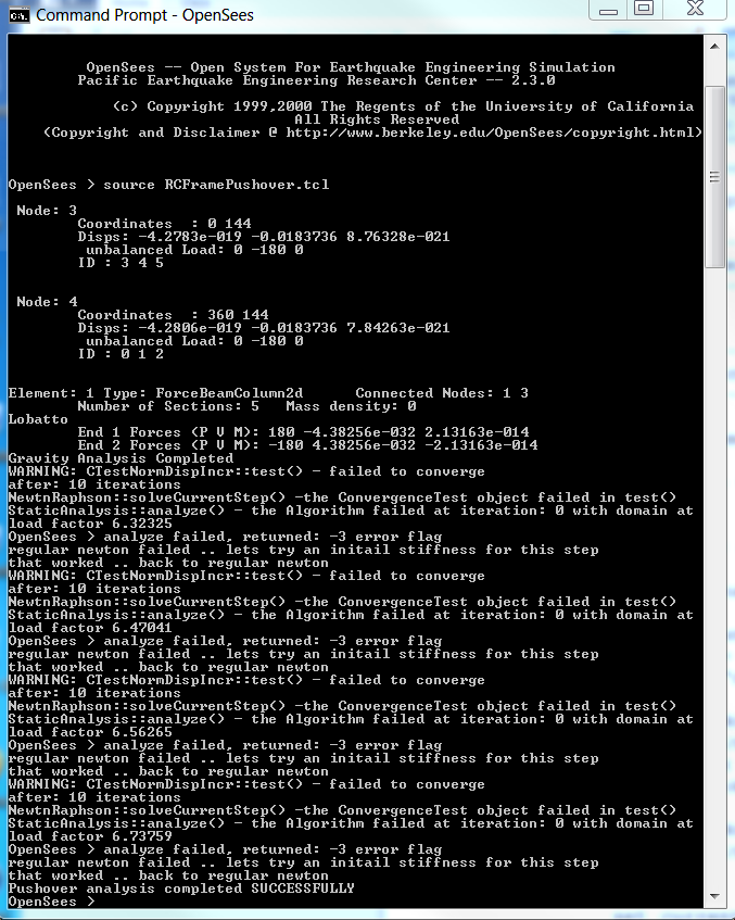
When the script is run the following will appear. | |||
[[Image:RCFramePushoverRun.PNG|link=RC Frame Results]] | |||
NOTES: | |||
# In the ouput you will notice the results of the print commands in the previous file. | |||
# You will also see a lot of warning messages. These are times within the analysis script that the analysis step has failed and the alternative initial step iterations are being performed. | |||
# The puts messgae at the end indicates that the pushover analysis was succesfull. | |||
[[Image:RCFramePushoverCurve.png|link=RC Frame Pushover Curve]] | |||
Latest revision as of 23:50, 8 May 2014
In this example the reinforced concrete portal frame which has undergone the gravity load analysis is now be subjected to a pushover analysis.
Files Required:
NOTES: This example demonstrates the use of Tcl programming in order to perform the nonlinear analysis. When dealing with nonlinear problems, the models do not always converge for the analysis options of choice. For this reason it is sometimes necessary to step through the analysis, checking for convergence at each step and trying different options if the analysis fails at any particular step. This script makes use of the fact that many OpenSees commands actually return values that can be used in the script.
Model
The RCFrameGravity script is first run using the "source" command. The model is now under gravity and the pseudo-time in the model is 1.0 [= 10 * 0.1 load steps]. The existing loads in the model are now set to constant and the time is reset to 0.0. A new load pattern with a linear time series and horizontal loads of magnitude 10.0 acting at nodes 3 and 4 is then added to the model.
It should be noted that when using a displacement control strategy, as we will employ in the pushover analysis, these horizontal loads are the reference loads that are being applied. The actual loads that are applied will equal these values multiplied by the load factor that the displacement control integration scheme determines is necessary to enforce the requested displacement.
# Do operations of RCFrameGravity by sourcing in the tcl file
source RCFrameGravity.tcl

# Set the gravity loads to be constant & reset the time in the domain
loadConst -time 0.0


# Define reference lateral loads for Pushover Analysis
# ----------------------------------------------------

# Set some parameters
set H 10.0; # Reference lateral load

# Set lateral load pattern with a Linear TimeSeries
pattern Plain 2 "Linear" {

        # Create nodal loads at nodes 3 & 4
	#    nd    FX  FY  MZ
        load 3 $H 0.0 0.0
        load 4 $H 0.0 0.0
}
Recorder
After the model as been created, but before the analysis is performed we will create two recorder objects. The first will record and write the nodal displacements and nodes 3 and 4 to a file named node34.out. The second recorder is an envelope element recorder that will write the envelope (max, min and abs max) of element forces at the 3 elements to a file ele32.out.
# Create a recorder to monitor nodal displacements
recorder Node -file node32.out -time -node 3 4 -dof 1 2 3 disp

# Create a recorder to monitor element forces in columns
recorder EnvelopeElement -file ele123.out -time -ele 1 2 forces
Analysis
For the Pushover analysis we will use a displacement control strategy. In displacement control we specify a incremental displacement that we would like to see at a nodal dof and the strategy iterates to determine what the pseudo-time (load factor if using a linear time series) is required to impose that incremental displacement. For this example, at each new step in the analysis the integrator will determine the load increment necessary to increment the horizontal displacement at node 3 by 0.1 in. A target displacement of $maxU (15.0 inches) is sought.
As the example is nonlinear and nonlinear models do not always converge the analysis is carried out inside a while loop. The loop will either result in the model reaching it's target displacement or it will fail to do so. At each step a single analysis step is performed. If the analysis step fails using standard Newton solution algorithm, another strategy using initial stiffness iterations will be attempted.
# set some parameters
set maxU 15.0;	        # Max displacement
set ok 0
set currentDisp 0.0

# perform the analysis
while {$ok == 0 && $currentDisp < $maxU} {

   set ok [analyze 1]

   # if the analysis fails try initial tangent iteration
   if {$ok != 0} {
       puts "regular newton failed .. lets try an initail stiffness for this step"
       test NormDispIncr 1.0e-12  1000
       algorithm ModifiedNewton -initial
       set ok [analyze 1]
       if {$ok == 0} {puts "that worked .. back to regular newton"}
	  test NormDispIncr 1.0e-12  10
	  algorithm Newton
       }
    }

    set currentDisp [nodeDip 3 1]

}

# spit out a SUCCESS or FAILURE MESSAGE
if {$ok == 0} {
  puts "Pushover analysis completed SUCCESSFULLY";
} else {
  puts "Pushover analysis FAILED";
}
Running the Script
When the script is run the following will appear.
NOTES:
- In the ouput you will notice the results of the print commands in the previous file.
- You will also see a lot of warning messages. These are times within the analysis script that the analysis step has failed and the alternative initial step iterations are being performed.
- The puts messgae at the end indicates that the pushover analysis was succesfull.